| Christ
Church Unitarian Chapel Bridgwater Somerset |
| Christ
Church Unitarian Chapel Bridgwater Somerset |
|
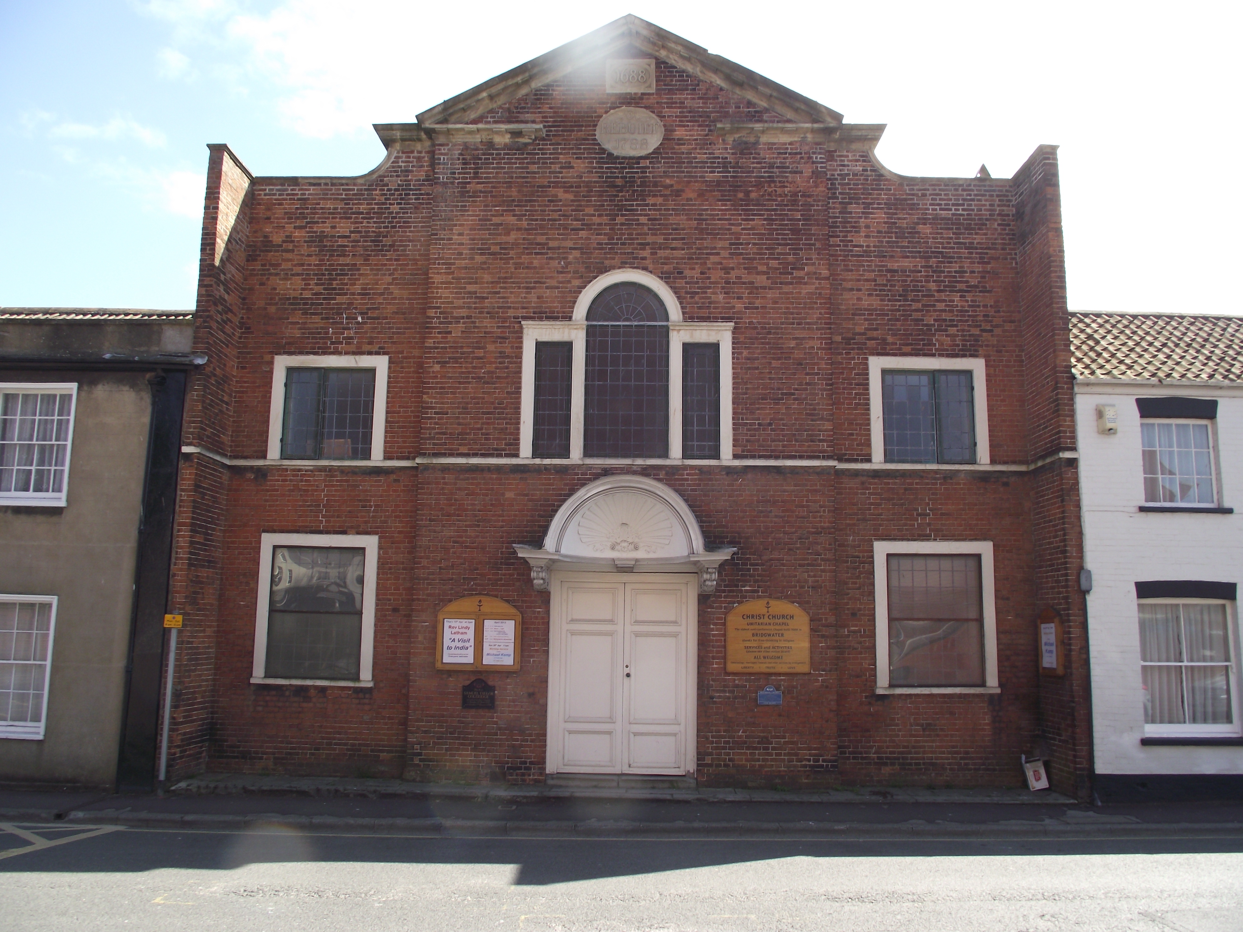
Christ
Church Unitarian Chapel is the oldest non-conformist
Chapel in Bridgwater there
being a building on this site since 1662. This first
meeting house was demolished in
1683 and its contents destroyed.
The meeting house as presently built was erected in 1688 with an extensive restoration carried out in 1788. The engineering services comprising gas lighting and central heating were installed during the Victorian period. The building was Listed Grade II* in 1950. |
|
The
Heritage Group was notified that the heating system
in this Chapel was thought to have a saddle
type wrot iron boiler still in situ. As saddle
boilers can date back to the early Victorian
era every one now discovered has historic and
engineering heritage importance.
A
site visit March 2013 by the Heritage Group was
arranged for an inspection of the Chapel
and its heating system. This wet system had remained
unchanged since its installation
in the mid-Victorian period circa.1860 and was
thought to have a most unusual
water circulation system. What was found became an
exciting discovery.
|
 |
 |
 |
 |
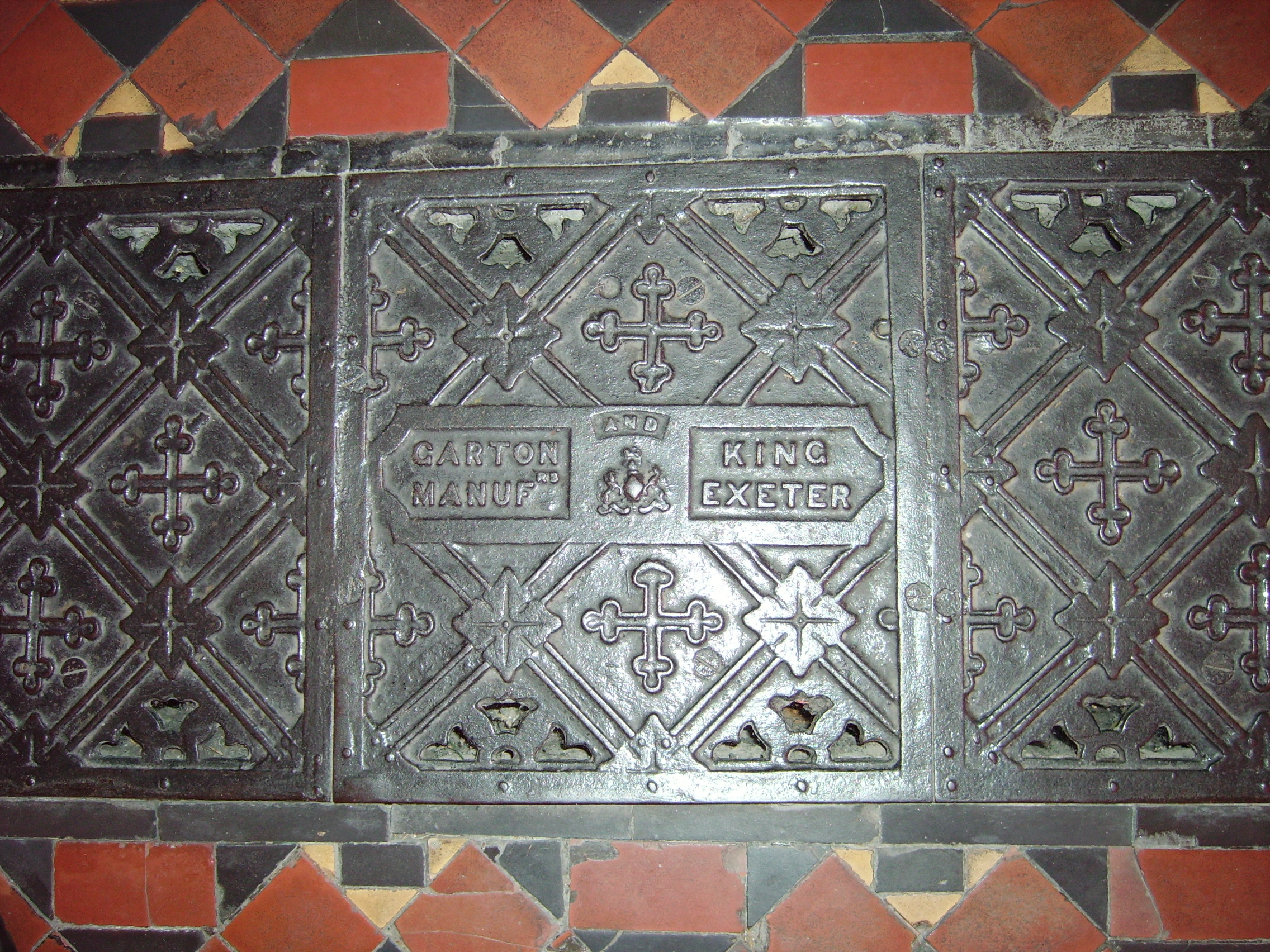
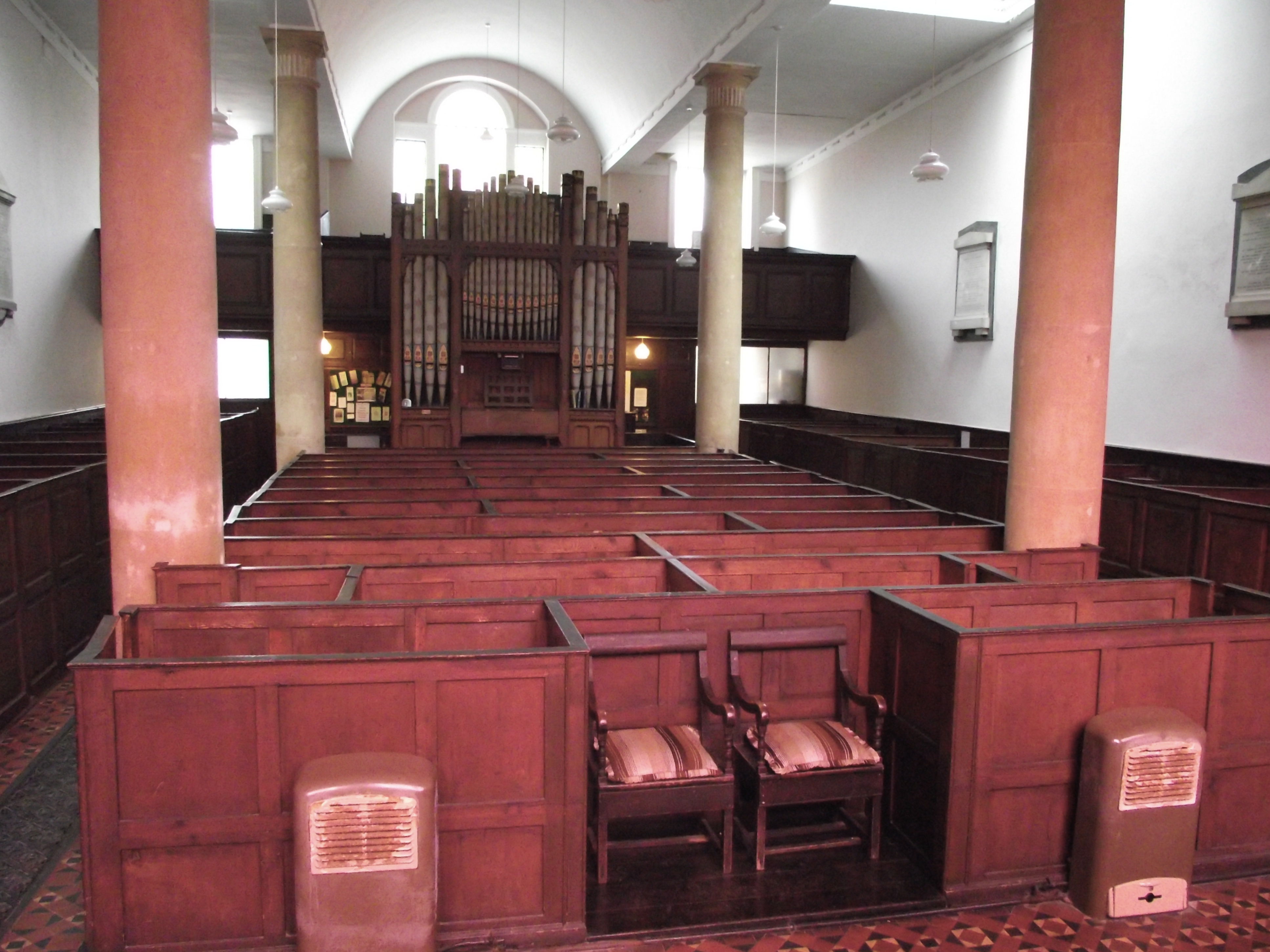
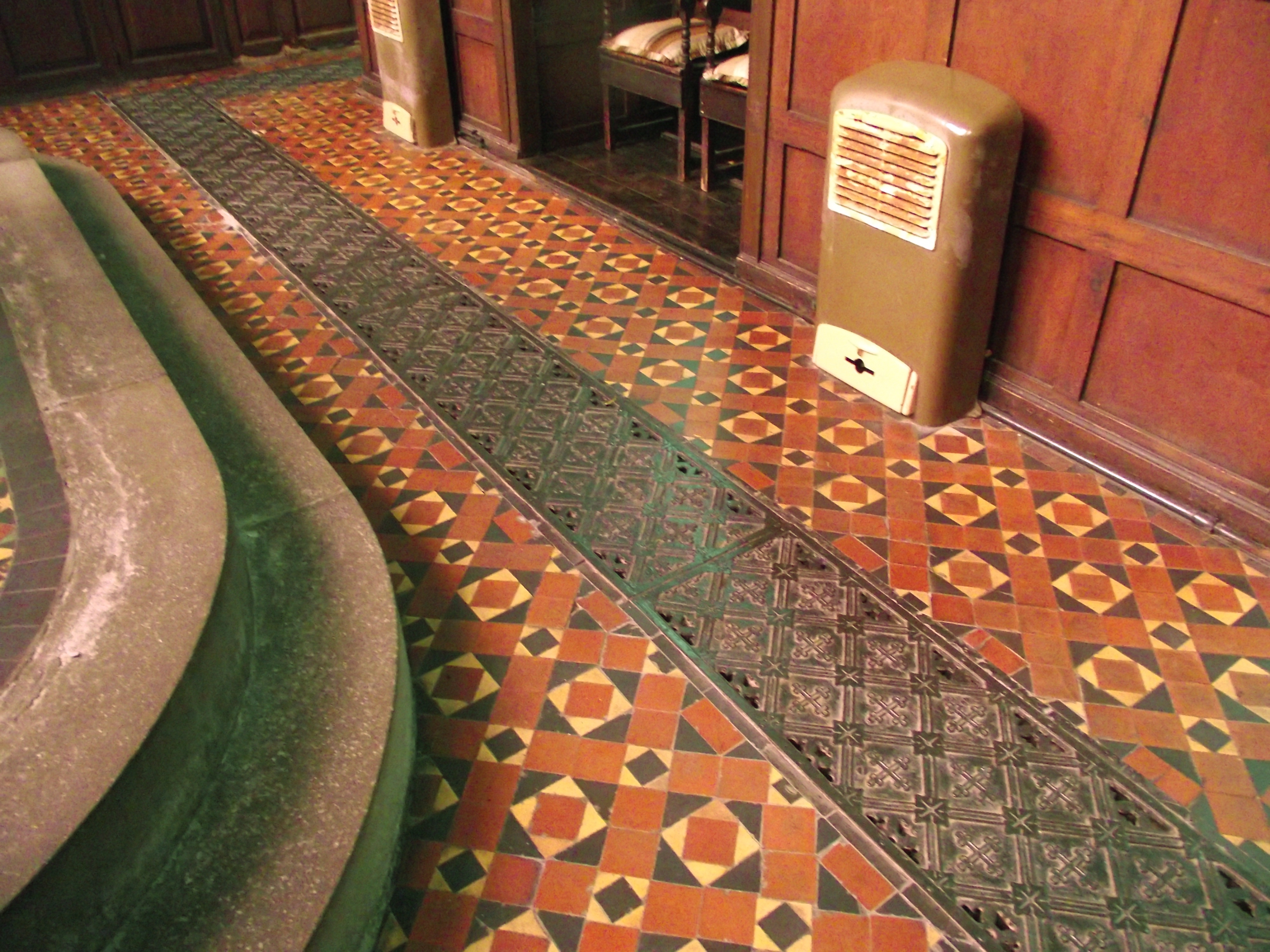
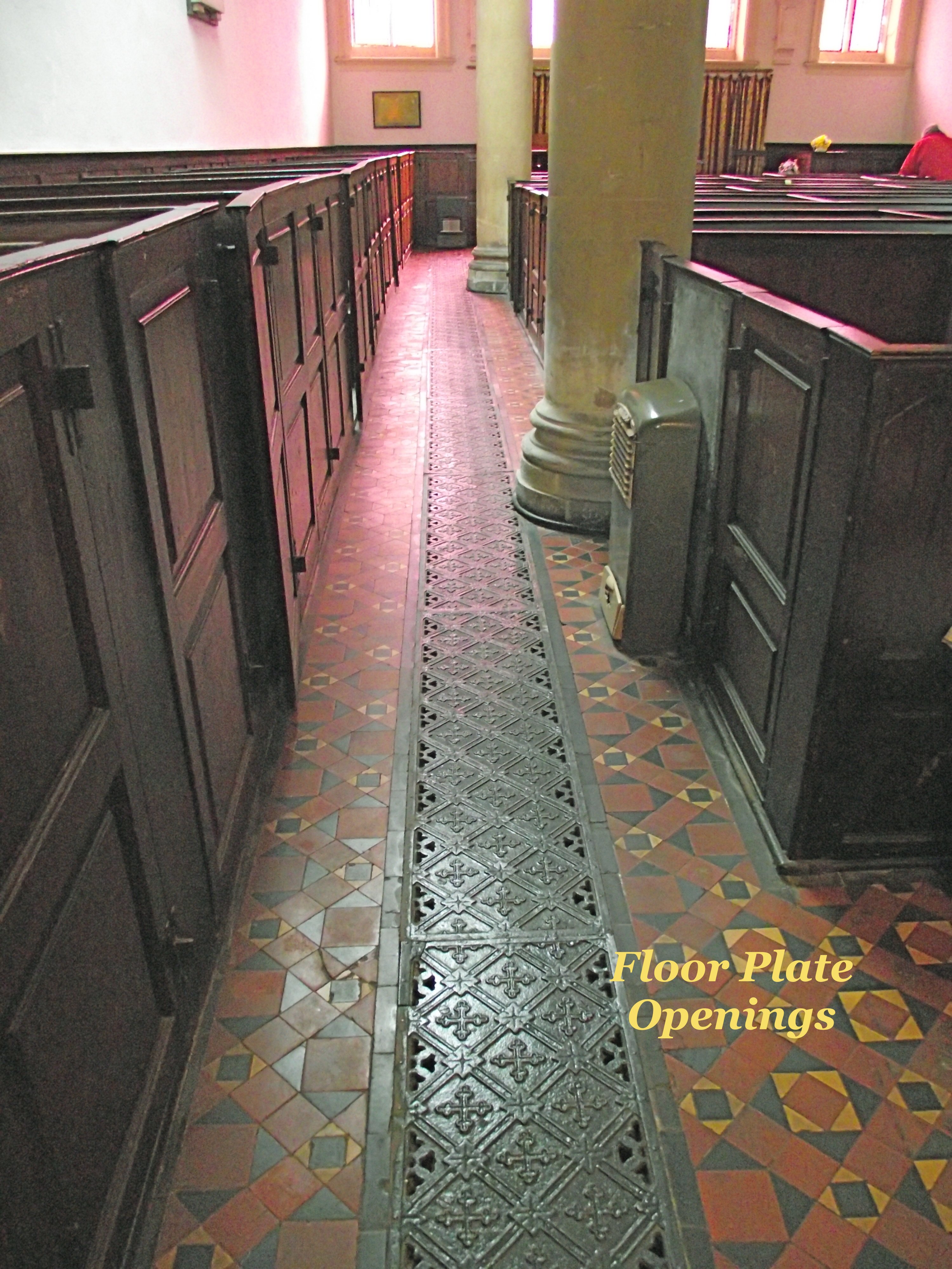
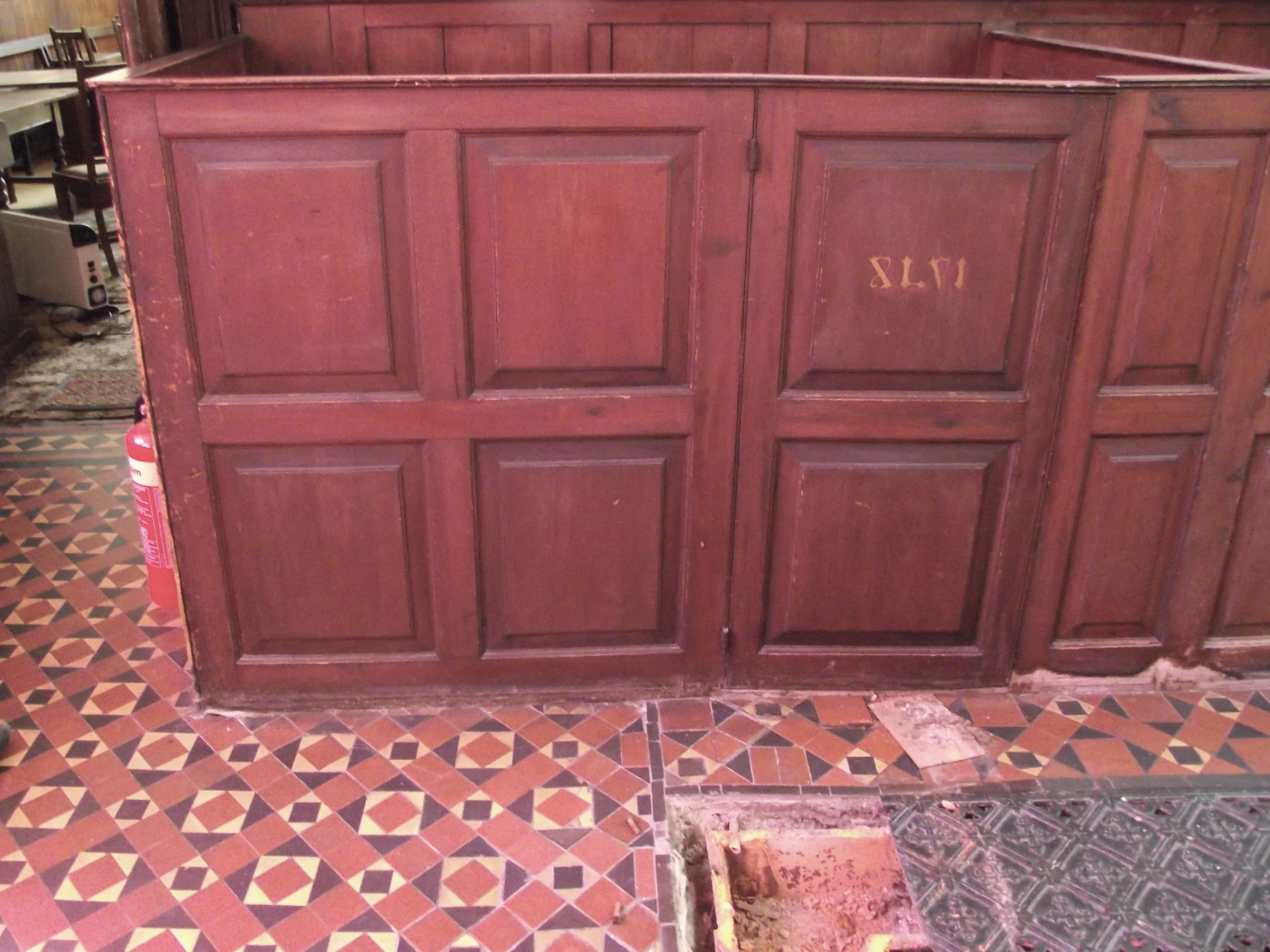
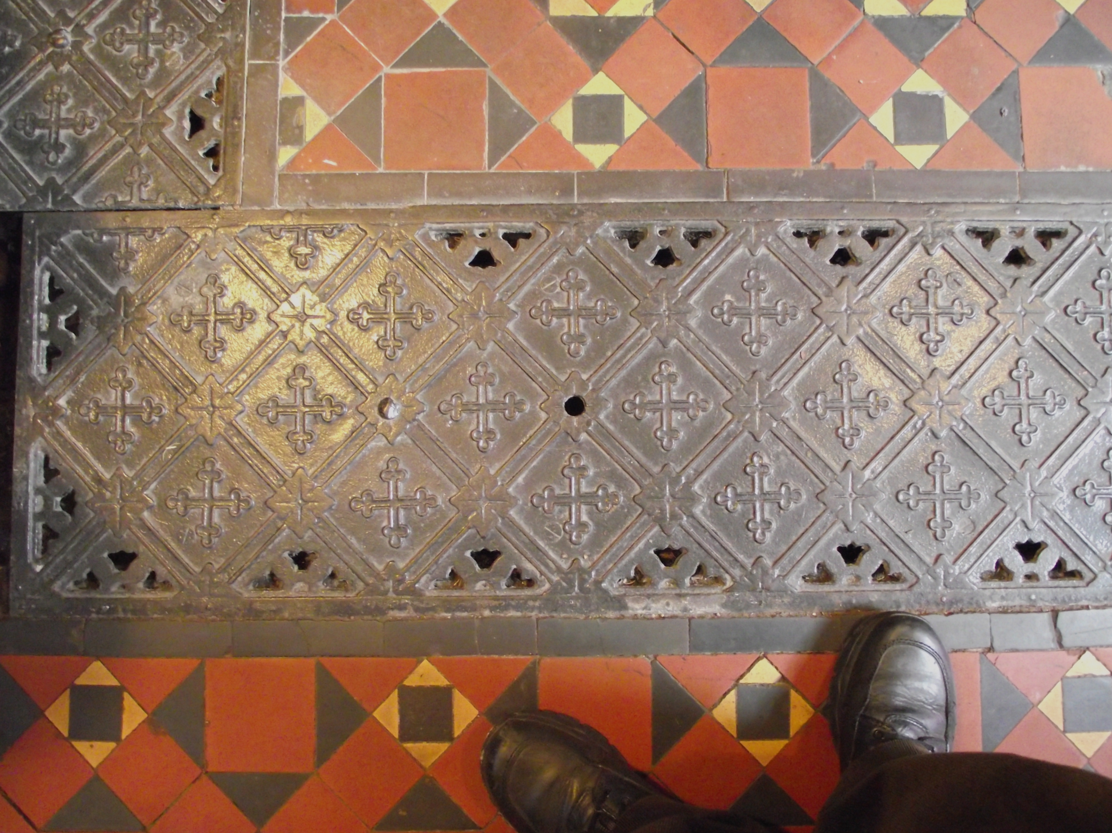
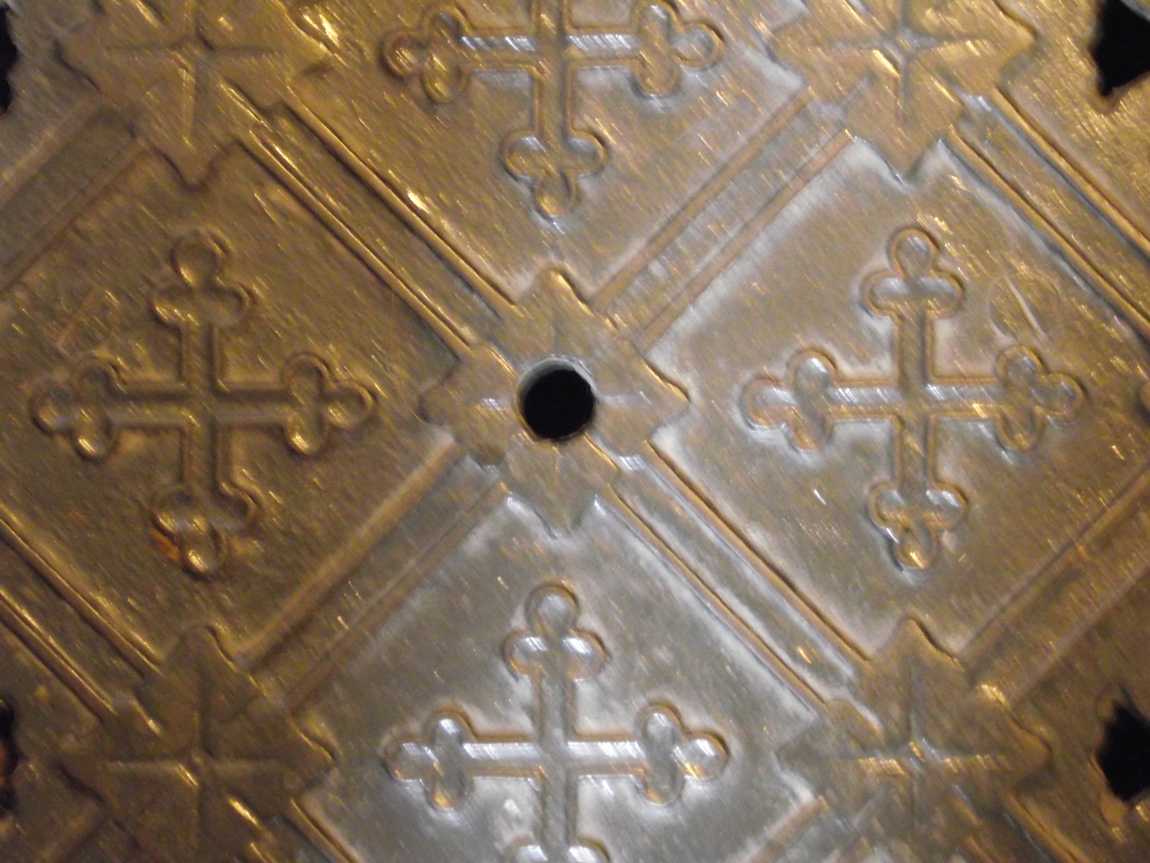
| The Chapel has four aisles forming a
rectangle around the building that allows access to
the box pews on either side. In the centre of the
floor of each aisle are laid decorative cast iron
floor plates with small openings along either edge.
The floor plates are laid in sections each approx
400mm wide by 1500 mm length. |

 |
 |
 |
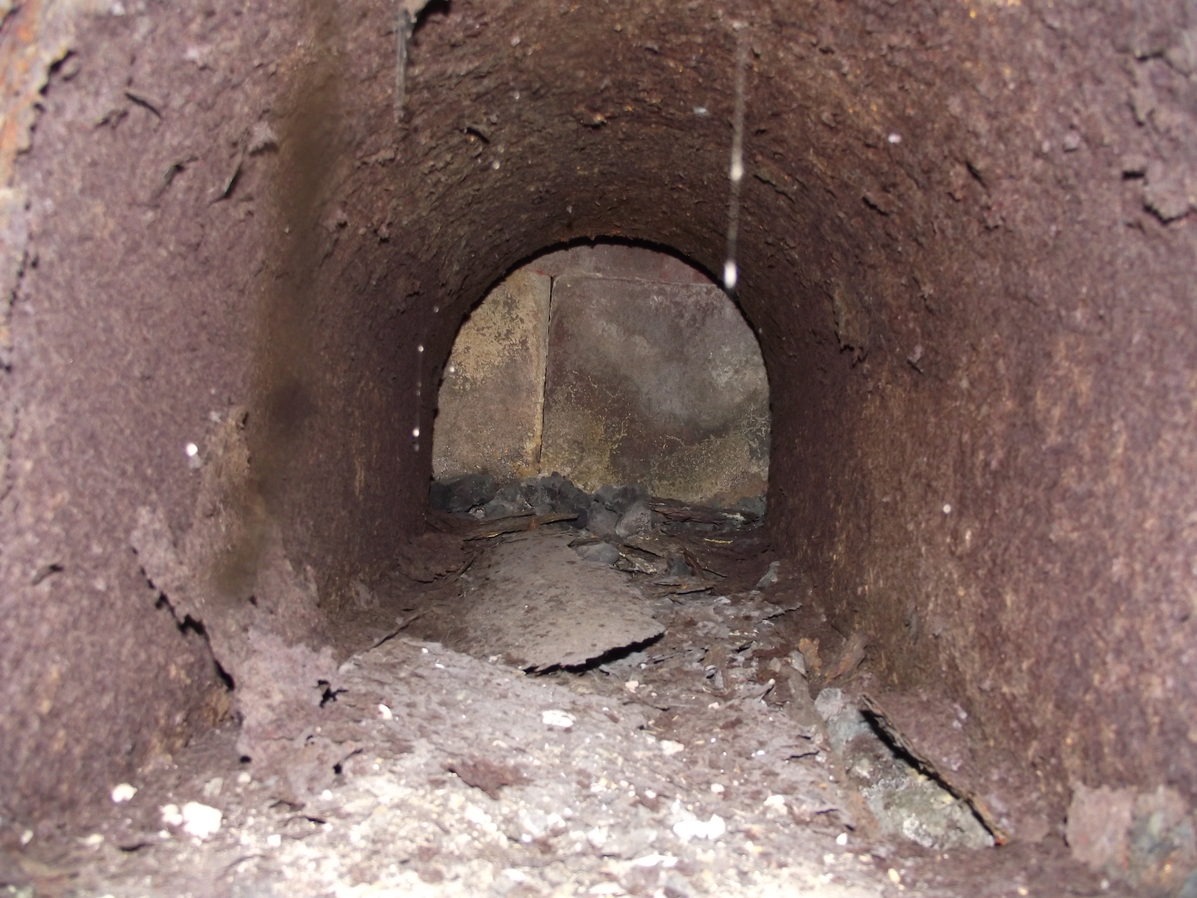 |
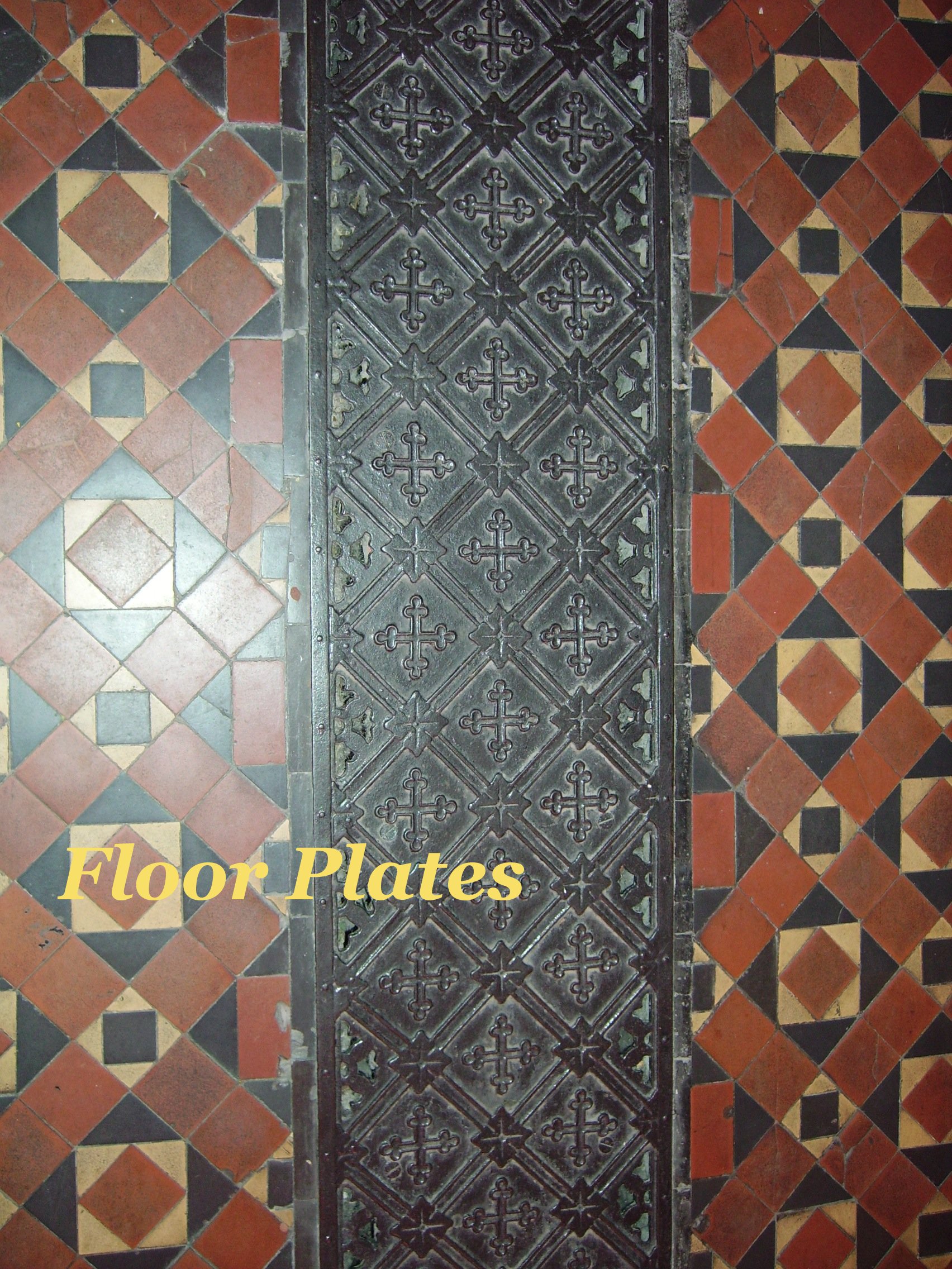
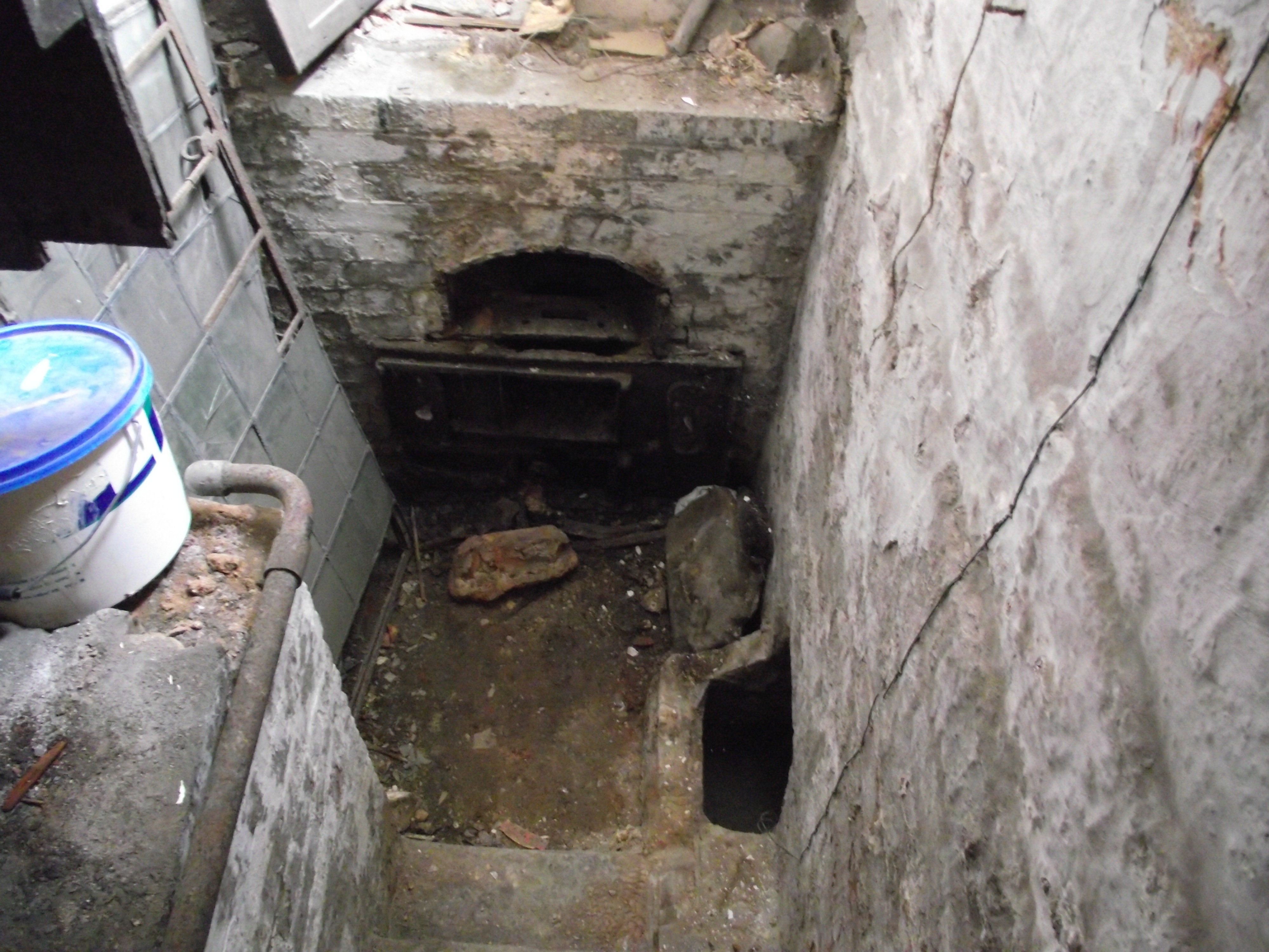
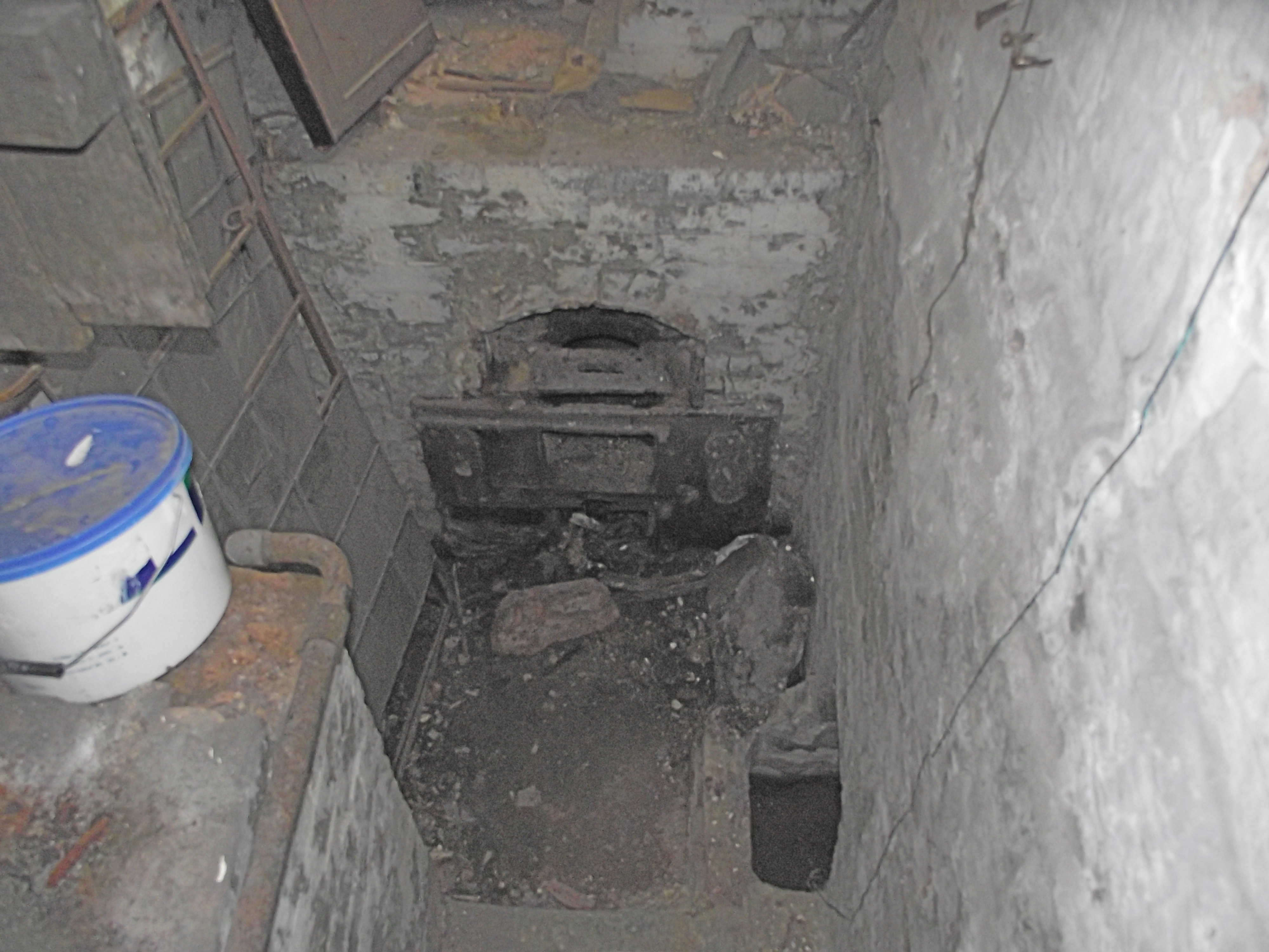
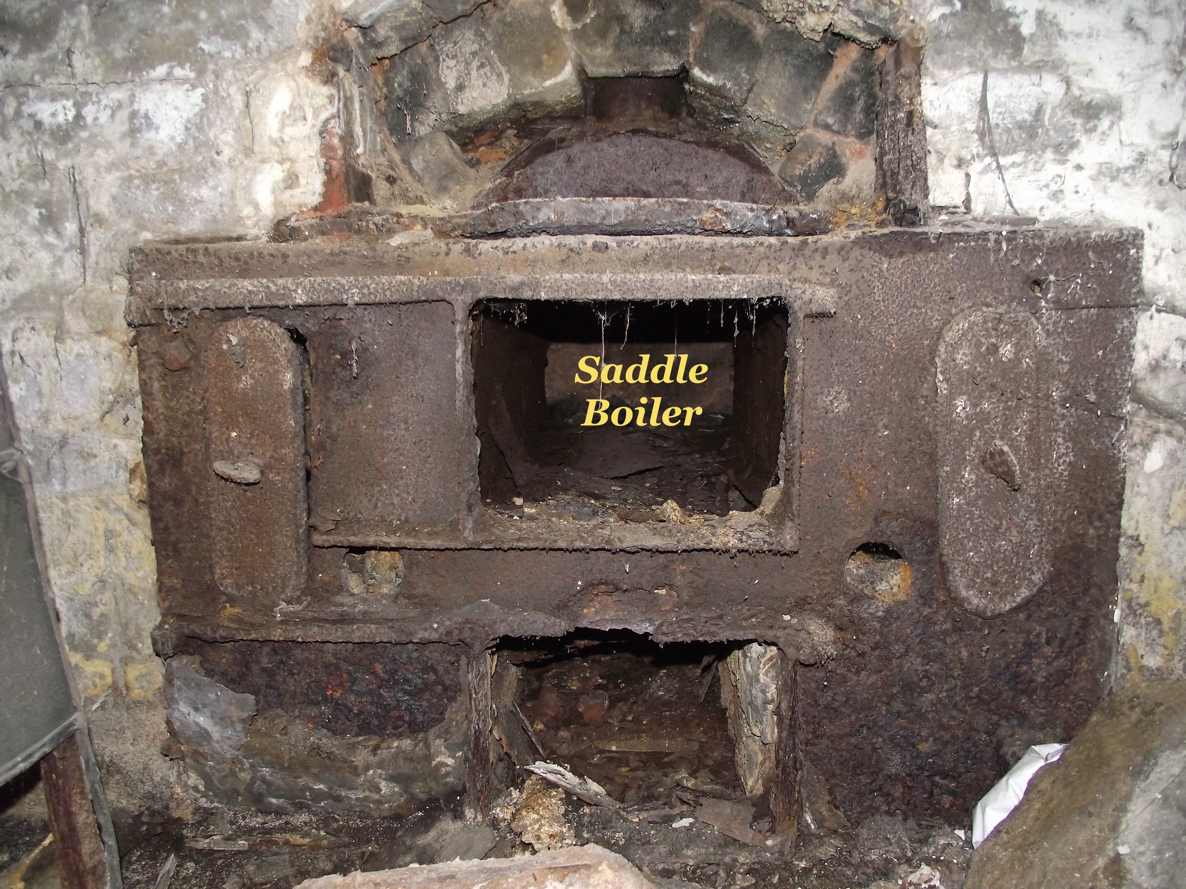
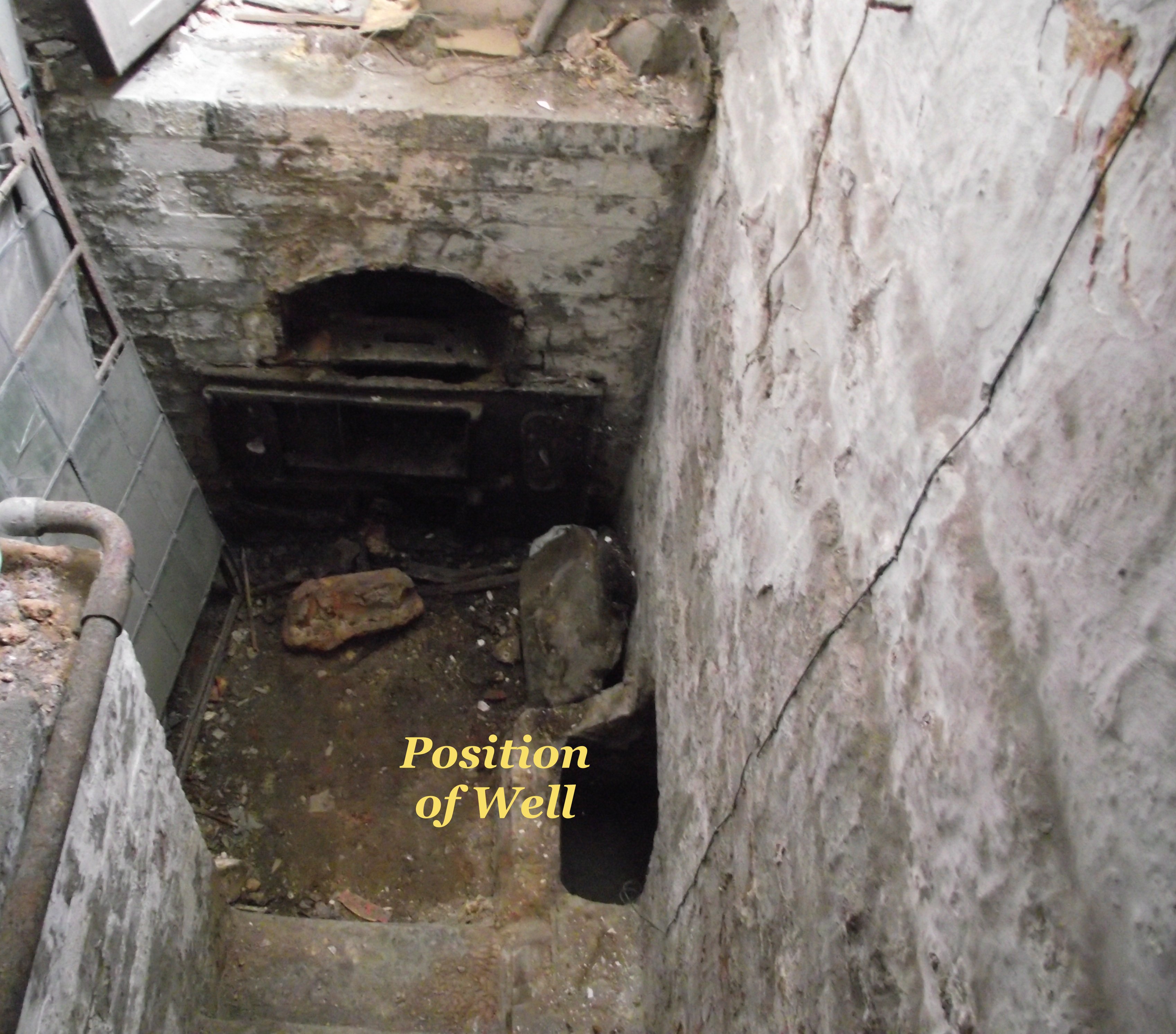
| The boiler for the
heating system sited in a small semi-basement room is
a saddle pattern set into brickwork, with flow and
return cast iron (CI) pipework laid within the
brickwork enclosing the boiler. There was no name inscribed on the boiler, but the decorative floor plates in the aisles of the Chapel bore the name Garton & King Manuft’s Exeter. This engineering firm was well known in south west England and had been in existence since the 17th century with their own ironfoundry operating since the 19th century. |
 |
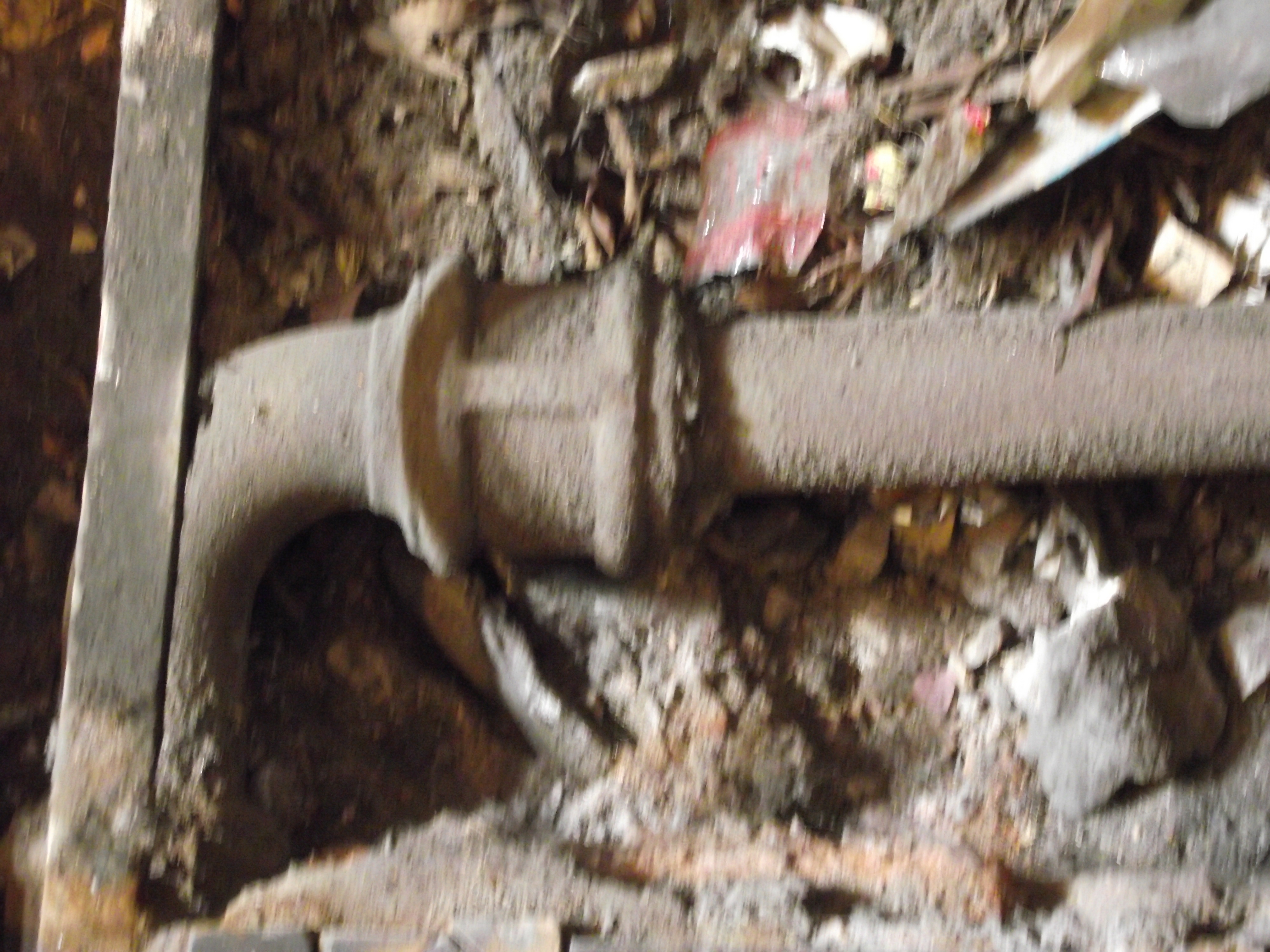 |
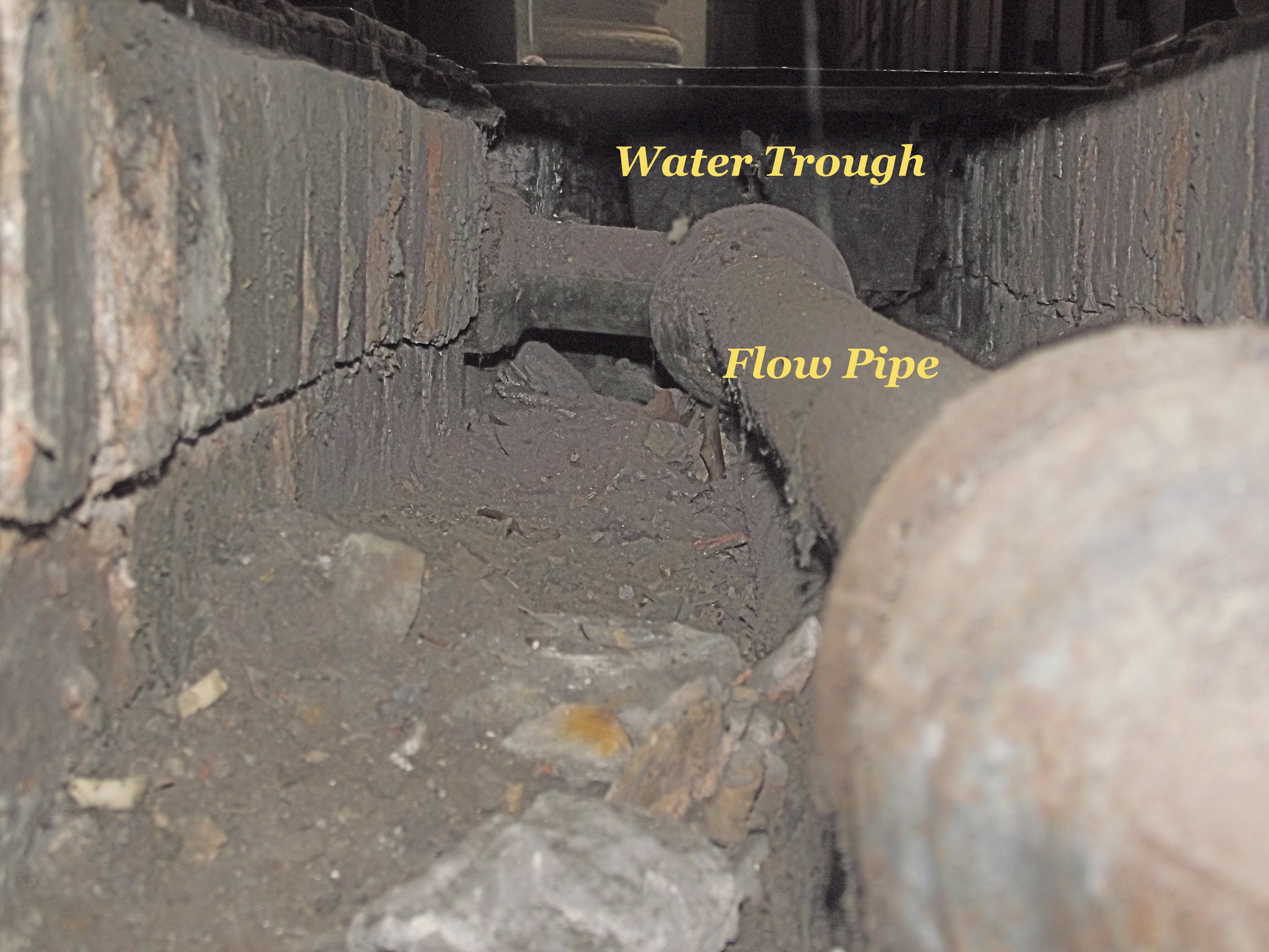
| The flow and return CI
pipework (approx 3” dia.) from the boiler then entered
into a small under floor duct. What then made this
heating system different and possibly unique was that
these two pipes appeared to connect directly to a
metal trough. |
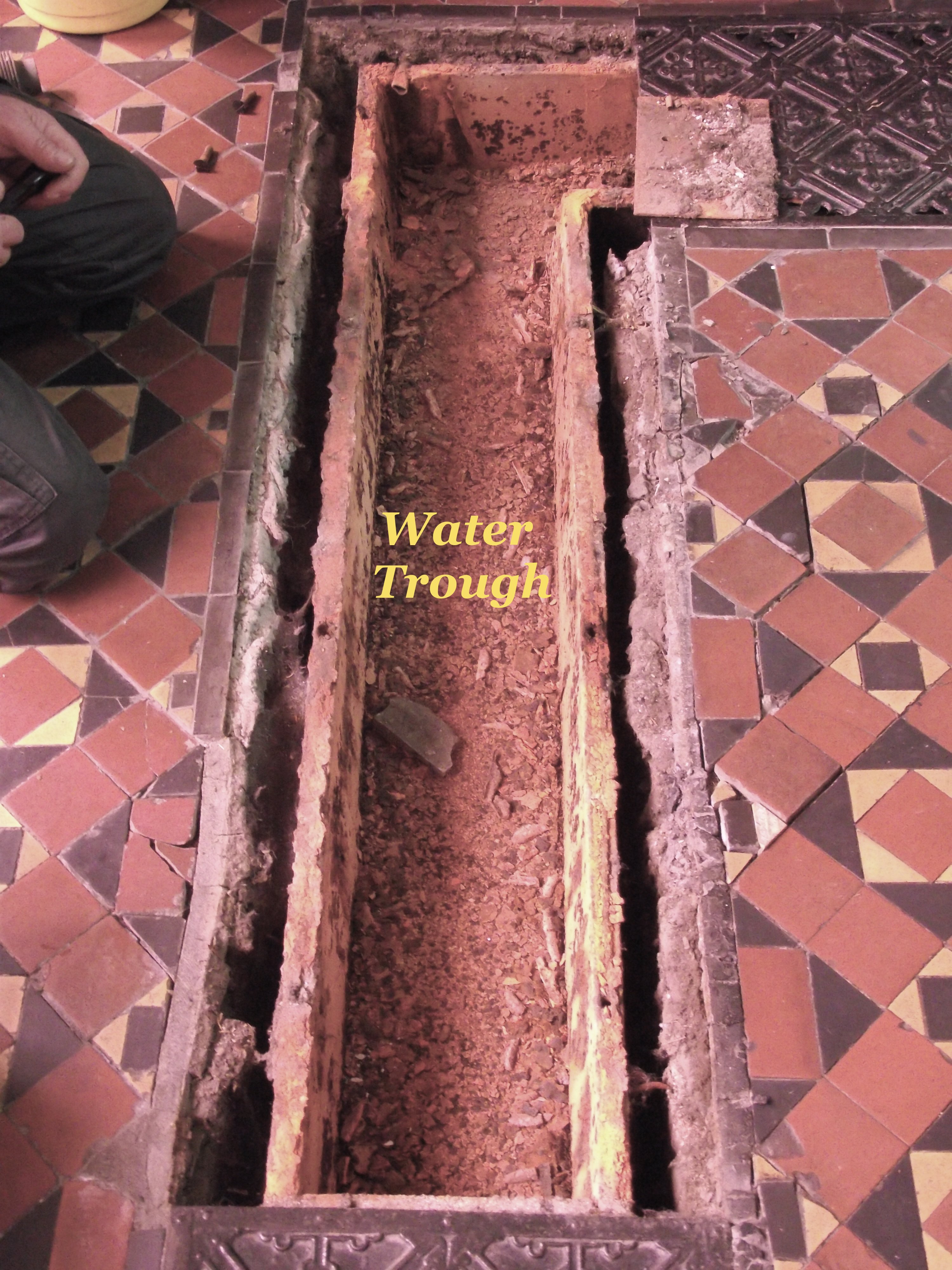
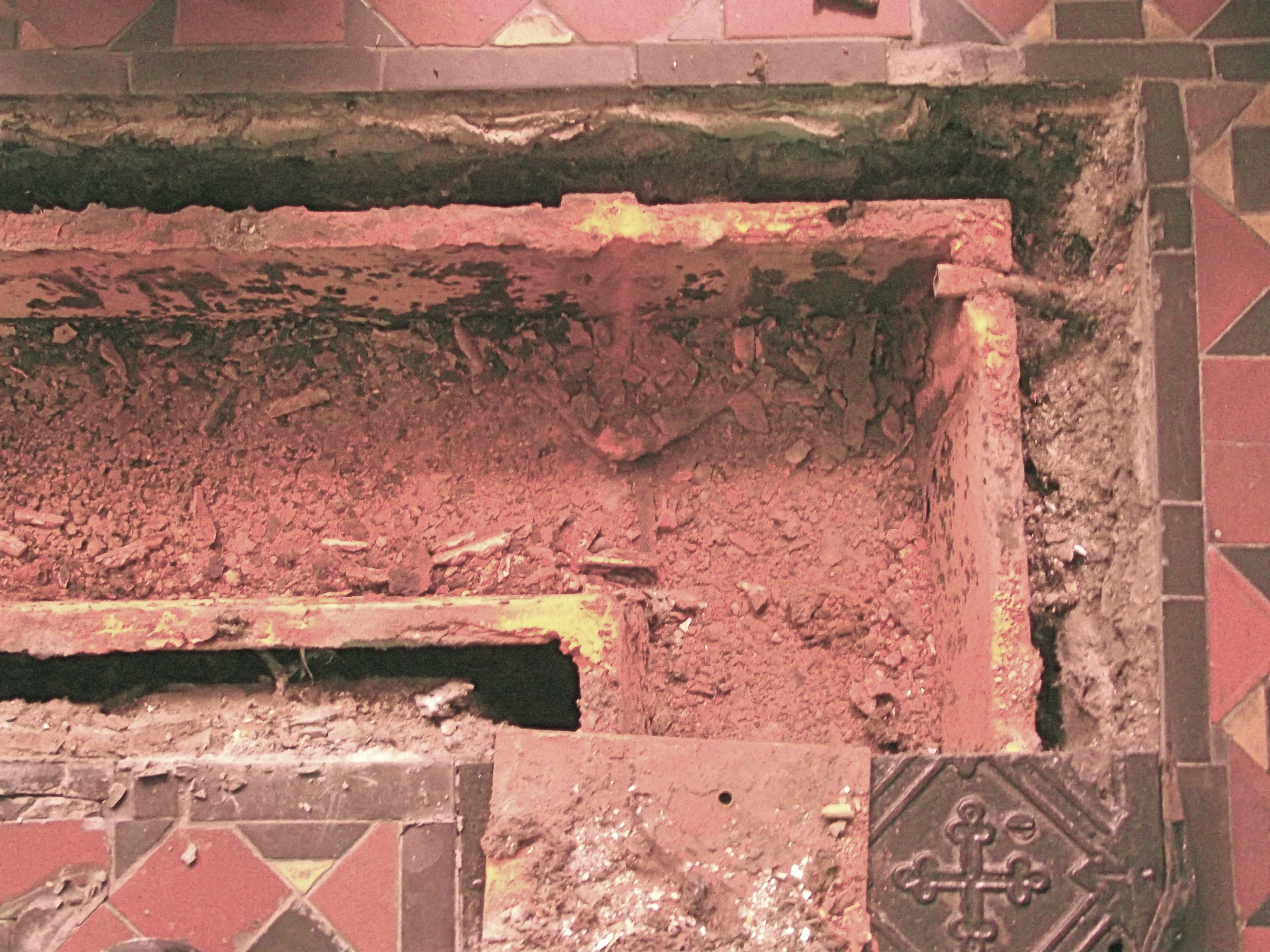
| Examination of the floor
plates showed that there was a cast iron metal trough
sited underneath. The trough was fitted tight to the
underside of the floor covers and secured to it by
screws. Each length of trough was constructed with one
end socket into which the spigot of the next section
was jointed by using caulking hemp/rope soaked in
black mastic. Both sides of the trough had flanged
tops with a slight grove into which was laid a hemp
rope soaked in black mastic. This sealed the top of
the trough when screwed to the underside of the plate
making the trough watertight. |
 |
 |
| The
metal trough (internal dimensions of 81/2 ins wide by 5
ins deep) would have been filled with water that
circulated by gravity circulation. The heating system
water circuit was arranged as a simple single loop
around the four aisles from and returning back to the
boiler. The floor surface of the four aisles is flat and level with no steps, so the water could only have circulated due to the circulating pressure created by the small height difference of approx 900 mm between the flow and return pipes connecting to the saddle boiler. |
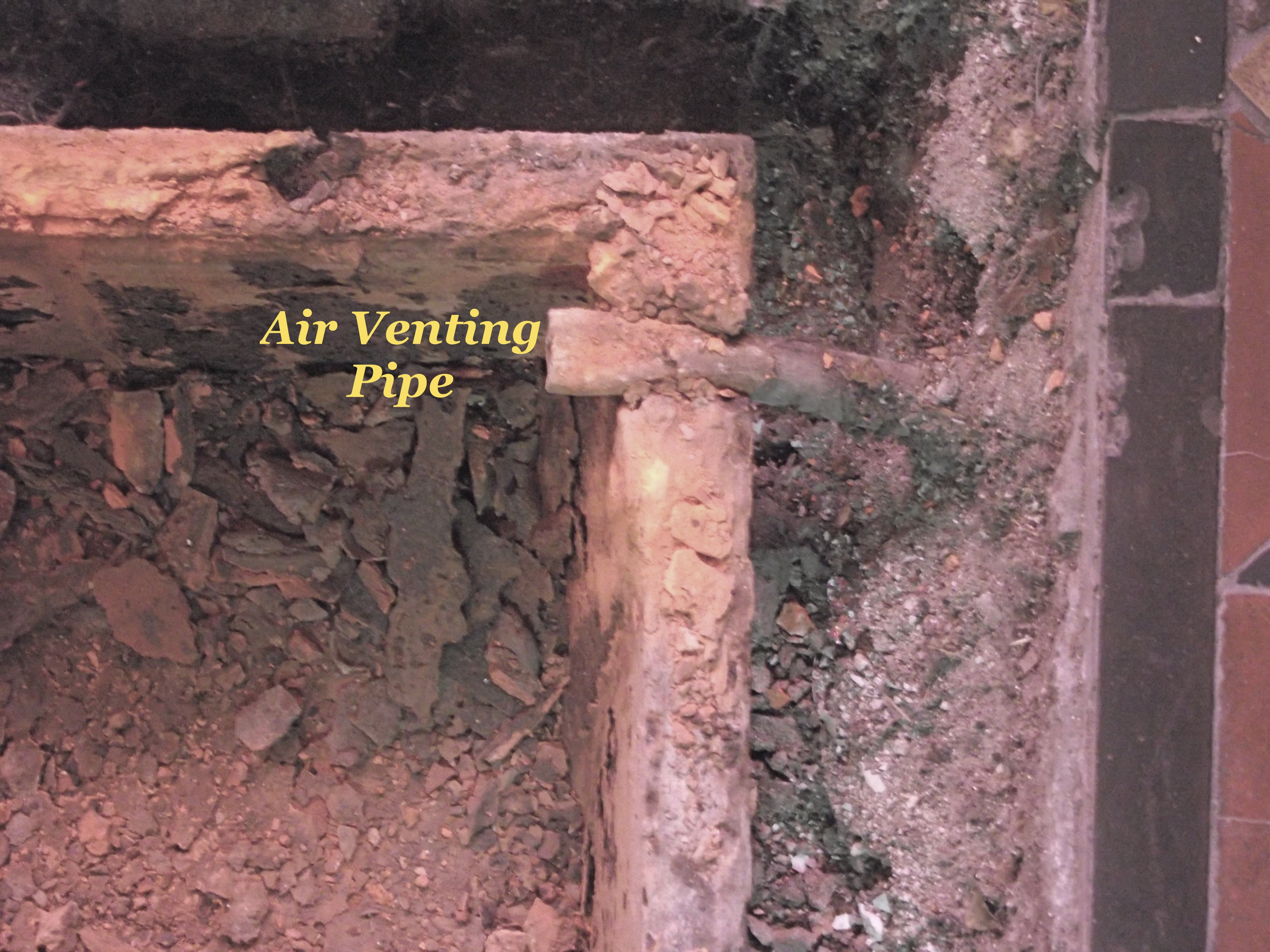
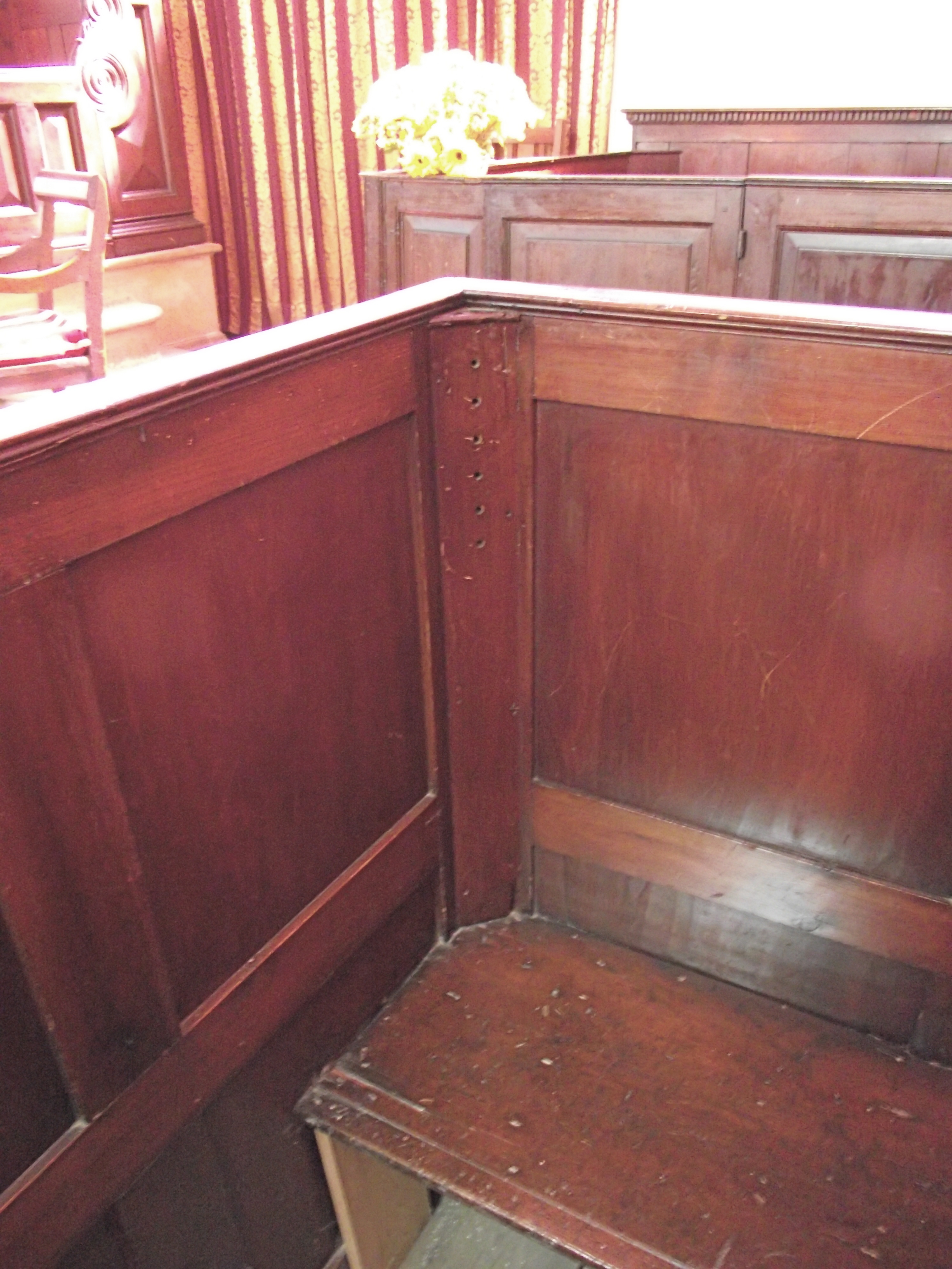
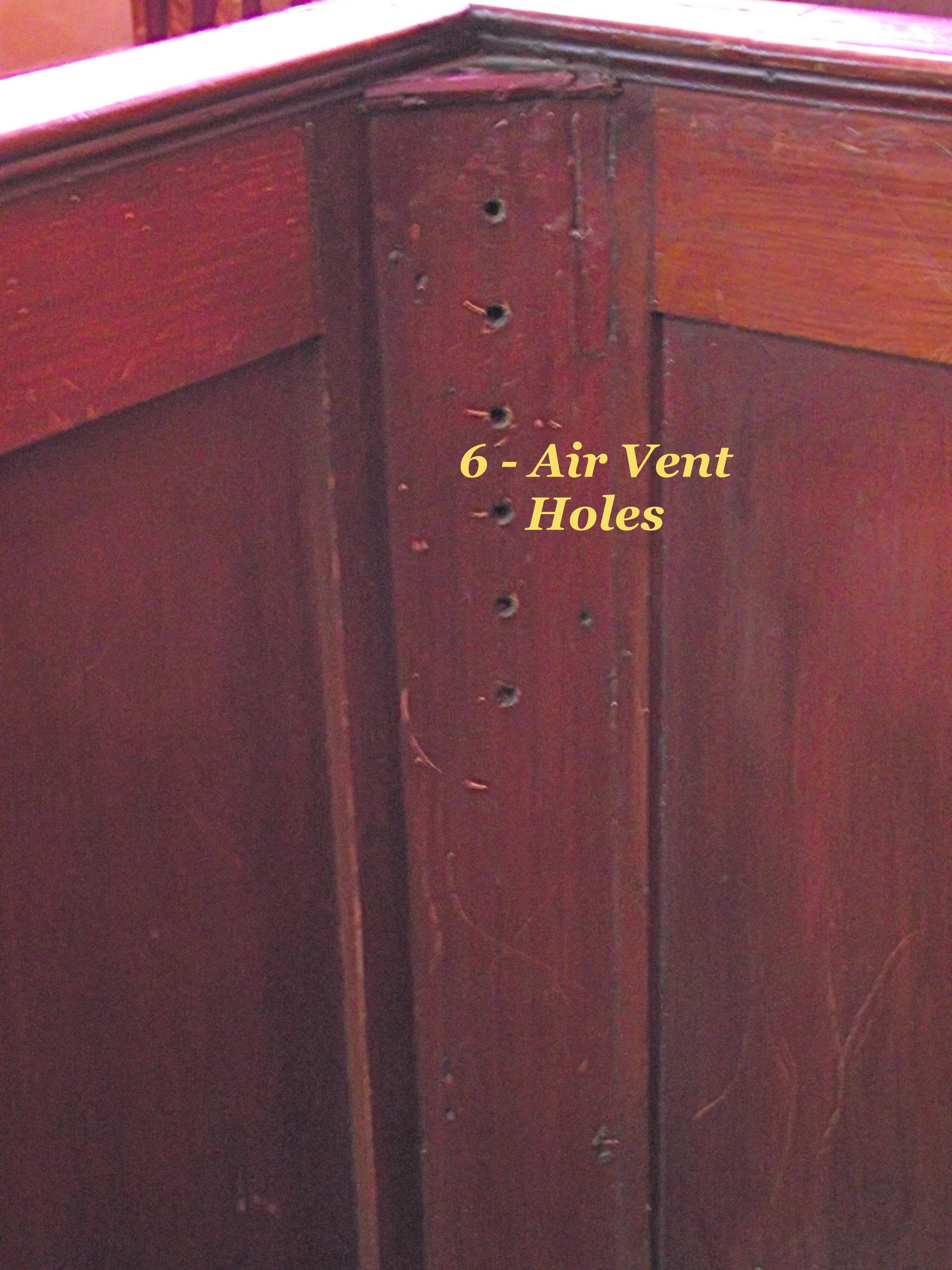
| Another strange feature
of this heating installation is that no obvious cold
feed or air vent pipework could be found. However upon
inspection, the two far corners of the floor trough
are each fitted with a small lead pipe having an open
end, placed into the top of the trough. These lead
pipes then rise up inside the end corner of the
adjacent box Pew, which has a series of small holes
drilled into the box pew corner. This appears to be
the means by which the sealed water trough was air
vented. |
 |
 |
 |
 |
| Another query was
deciding what method could have been used for filling
the water trough. Inspection of the decorative floor
plates found a number of small
circular holes drilled in the centre of
the plate that could have been used as filling
positions. The holes are located in one aisle at the
start of the trough on the flow side, with similar
openings at the end of the trough on the return. These
circular holes could have held a funnel through which
the water was poured. Dip-sticks would have been used
to measure the correct depth of water. Removable plugs
could then be fitted in the holes. |
 |
 |
| Where
did the water come from that was needed to originally
fill the system. In the semi-basement room close to the
boiler is an open Well full of water. This Well must
have provided the water used to fill the whole system,
most probably by bucket. The quantity of water
calculated to fill the trough would have taken approx
100 normal size buckets. |
|
To
have had any positive effect in raising the space
temperature of the Chapel would have required the
circulating water to have been very hot to maximize
the radiant and convective output. The high surface
temperature of the floor plates may have been
capable of causing a skin burn if
touched.
The saddle boiler was solid fuel fired with no safety or temperature controls fitted, so the overall control of boiler temperature and its output was at the discretion of the person acting as the stoker fireman. To start the water contents of the system moving and achieve an initial gravity circulation must have required the boiler flow temperature to be very high close to boiling point. Otherwise there would not have been sufficient temperature difference between flow and return pipes to “kick start’ the circulation. Whether
this
new method of circulating hot water was capable of
providing sufficient heat to raise the air
temperature in the Chapel to an acceptable comfort
level is questionable. The water circulating in the
trough could only transfer its heat to the occupied
space above firstly, by conduction and radiation
from the warm surface of the floor plates, and
secondly by convection through the small openings in
the sides of each section of floor plate.
As
the building would have had intermittent usage, the
length of pre-heat time would have been
disproportionate to achieve the required space
temperature. Most likely the boiler when started at
the commencement of the heating season would have
remained alight and only banked down during the
period when the Chapel was not in use. This method
would have kept the large quantity of water in the
trough always warm never allowing it to become cold.
The success of this method of circulating hot water around the building is highly debatable. So the search must continue to discover other Garton & King heating systems from the Victorian period having a similar water circulatory system. Until another system is found then the assumption must be that this new method was most likely a one-off that proved to be unsuccessful. |