Webpages under construction

| BRISTOL COUNCIL HOUSE |
|
The Council House
with its two roof mounted gilded Unicorns and facing
moat, that stands behind College Green is viewed by
Bristolians as an iconic building, and well worthy of
its Grade II* Listed status.
The selection of this site was first mooted in 1919 and then acquired in 1933 with Mr. E Vincent Harris commissioned as the Architect. Messrs William Cowlin & Son a Bristol firm of builders were appointed as the Main Contractor and site clearance work commenced in 1934. The foundation stone being laid in 1935. Cowlin's had completed the shell of the building by 1939 when the outbreak of WWII brought building operations to a stop. During the period of the war the building was temporary utilized as a “British Restaurant” to provide cheap meals for city workers, also used as a club for Services personnel and a storage area for emergency clothing supplies. The building was officially opened by HM the Queen on 17th April 1956. |

To read a copy of the following original documents pertaining to
the Engineering Services for the Council House click on any of
the three links below.
Specification for the Engineering Services Installations dated April 1937
Working (Operating & Maintenance) Instructions for the Engineering
Services dated approx. 1955
Electricity Agreement between SWEB and Bristol Council dated 1955
DESCRIPTION OF THE ORIGINAL ENGINEERING SERVICES
|
Central Heating
The engineering
services were designed by a London Consultantcy J
Roger Preston & Partners. They commenced
their design of the various mechanical services from
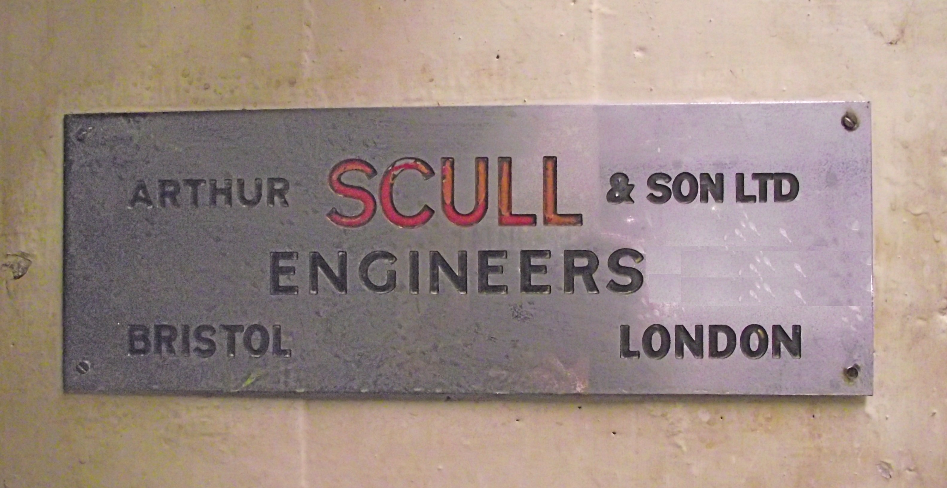
1936 onwards. A local Heating & Ventilating firm
Arthur Scull & Son submitted the successful tender
and was appointed as the Mechanical Services
Sub-Contractor.
The basement heating plant that includes the electrode boilers and storage vessels are still in situ complete with their associated pumping equipment, electrical control panel, automatic temperature controls, instrumentation and distribution pipework. To discover a wet heating system of this size fed by off-peak electricity, installed in the 1950’s which remained in operation until approx 2004, is a very rare occurrence, and therefore of significant historical importance. This original central heating was replaced approx 2004, by a LPHW system with gas fired modular boiler plant sited in the roof space. The new distribution pipework was designed as a downfeed 2-pipe distribution arrangement serving radiators. All the existing Warm Air Ventilation systems were retained and connected to the new heating system. |
| The
choice of this method for central heating a building
is unusual for the 1930’s in that it is an electrical
off-peak LPHW wet heating system. The system used two
vertical pattern electrode boilers which used
electricity during the night time period from approx
10.00pm to 7.00am. The boilers heated water over-night
which was pumped to six 9000 gallon storage vessels
that acted as a thermal store for the heated water. Bristol Corporation as it was known at that time, had part ownership of Portishead Power Station and could therefore negociate a reasonably advantageous tariff for the cost of the off-peak electricity. This obviously influenced the choice of the heat generation plant. |
|
The
electrode boilers are Sulzer Bros. manufacture using
an electric supply of 6.6 kv from a dedicated
transformer, which served the Council House
building. The boilers have top adjustable electrodes
that can be motor driven down into the boiler shell
to respond to the building’s varying heating demand
in relation to the difference in external ambient
temperatures, experienced throughout the heating
season.
|
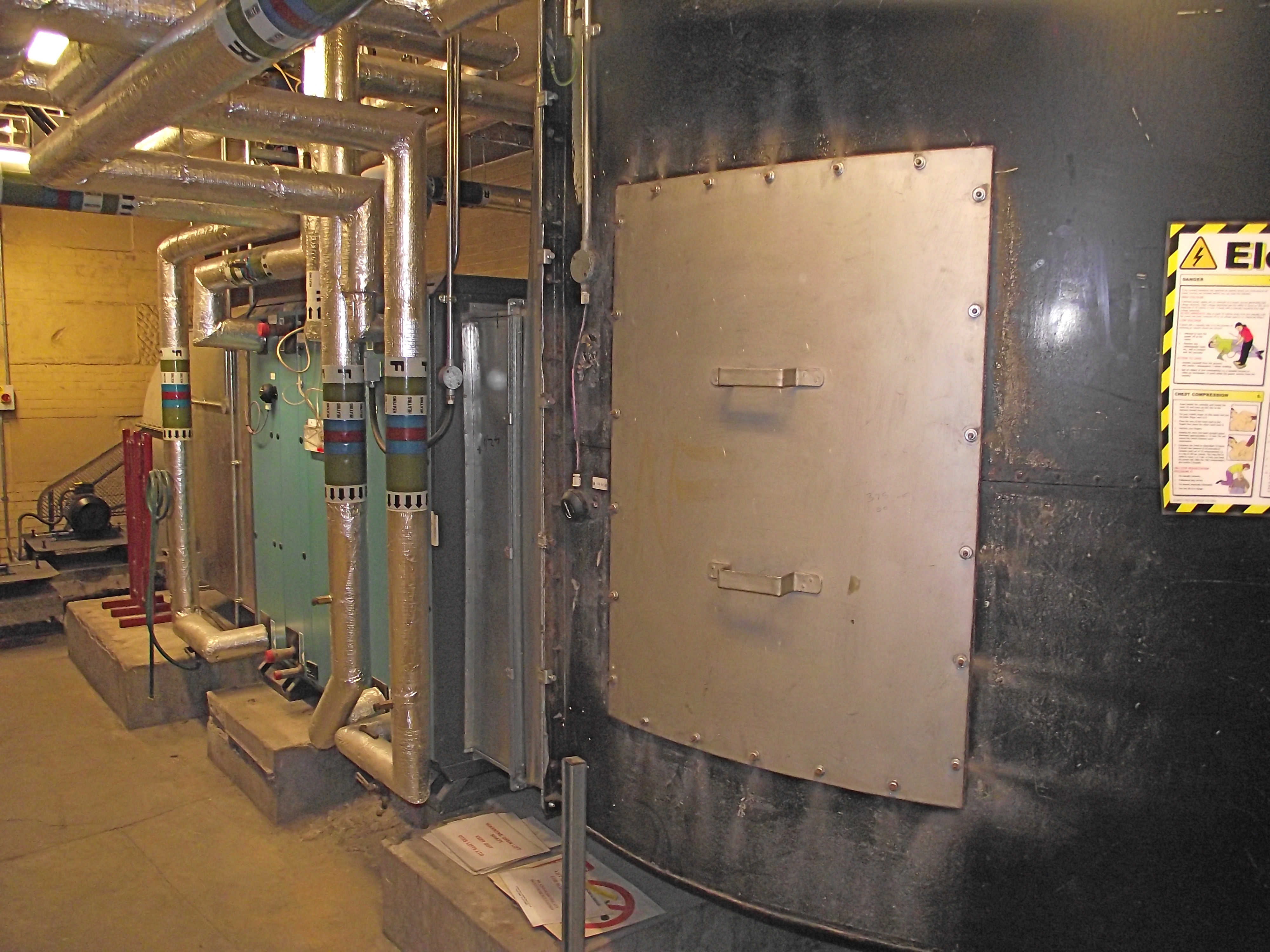
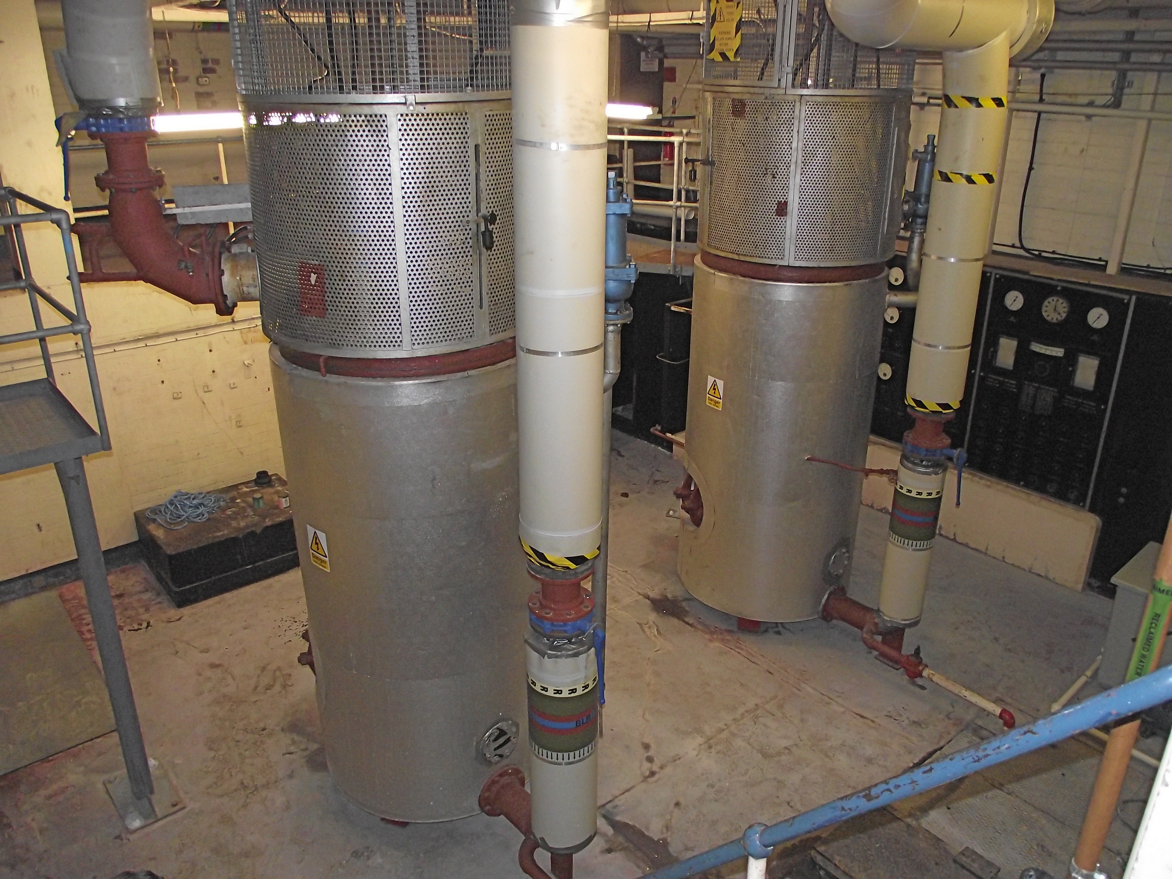 Electrode Boilers rear view |
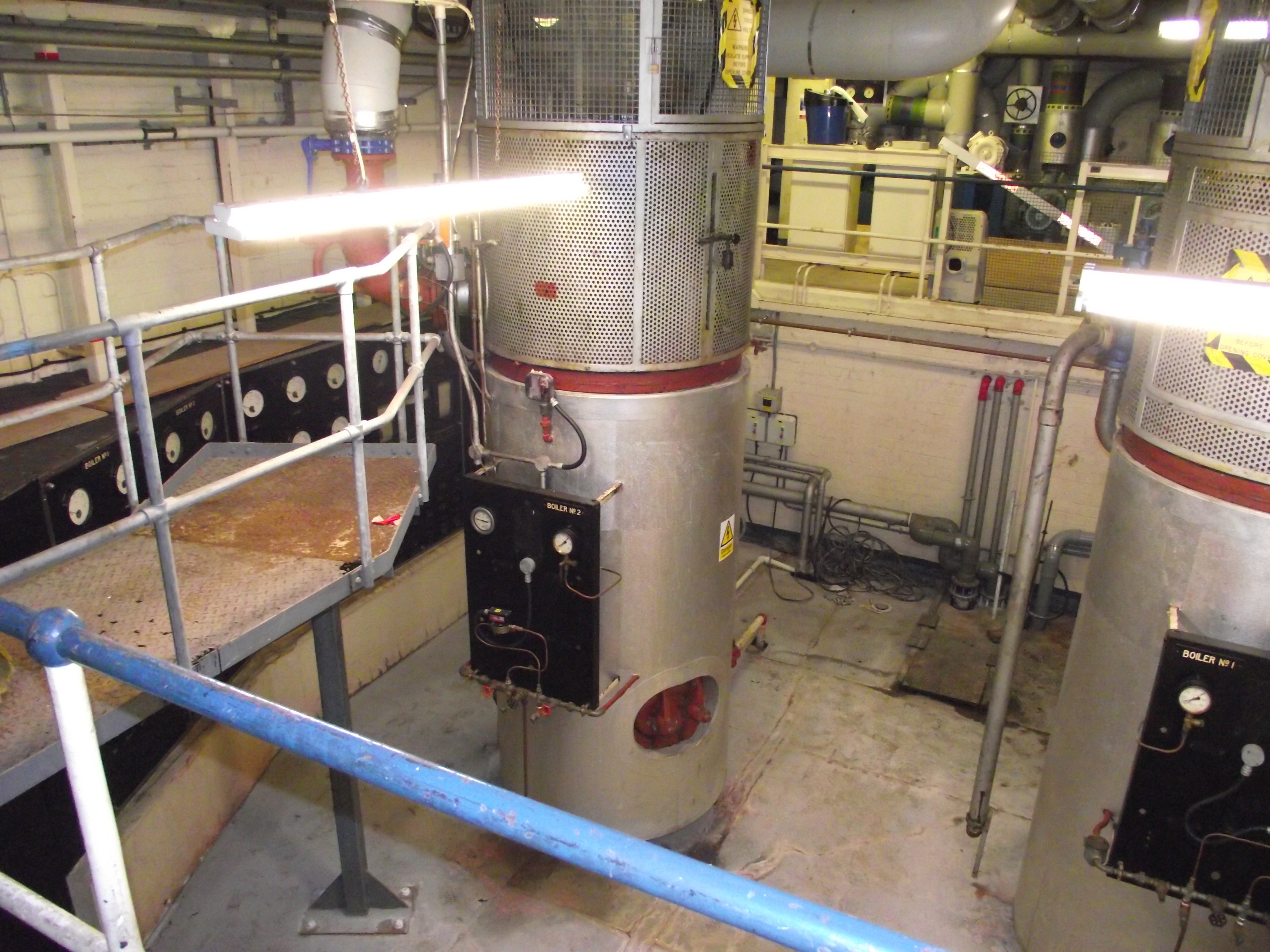 Electrode Boilers front view |
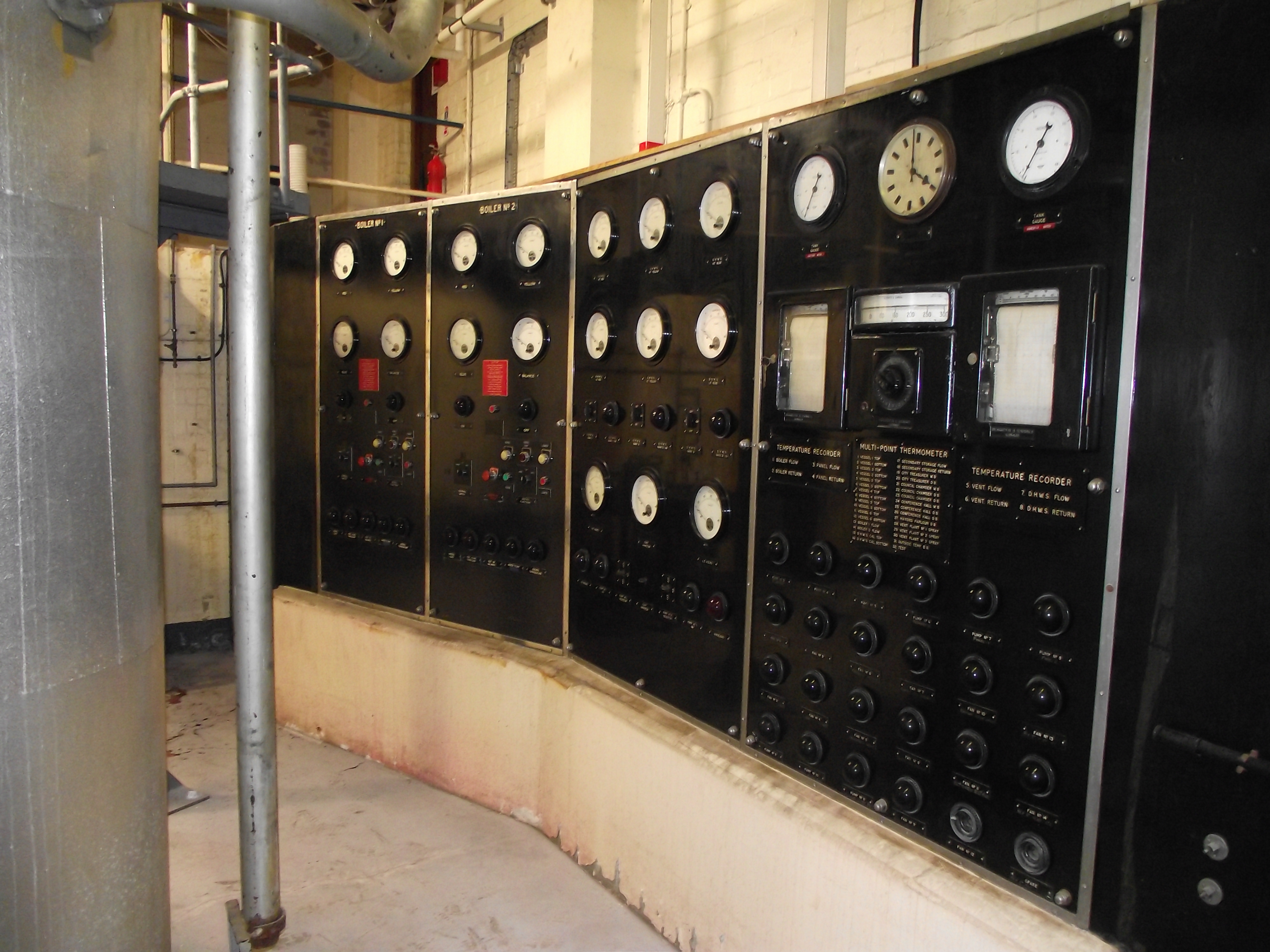 Main Boiler Control Panel right hand view |
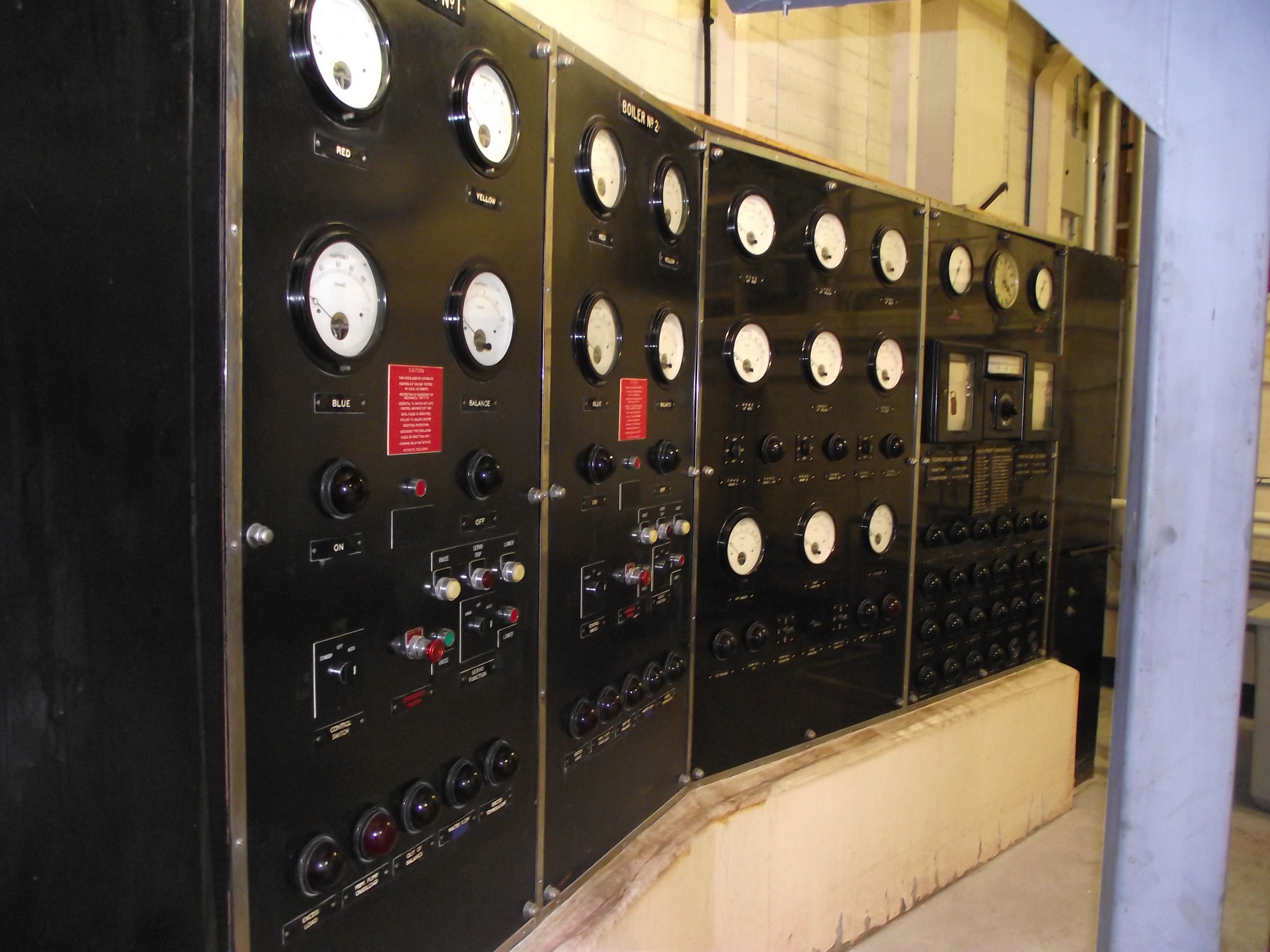 Main Boiler Control Panel left hand view |
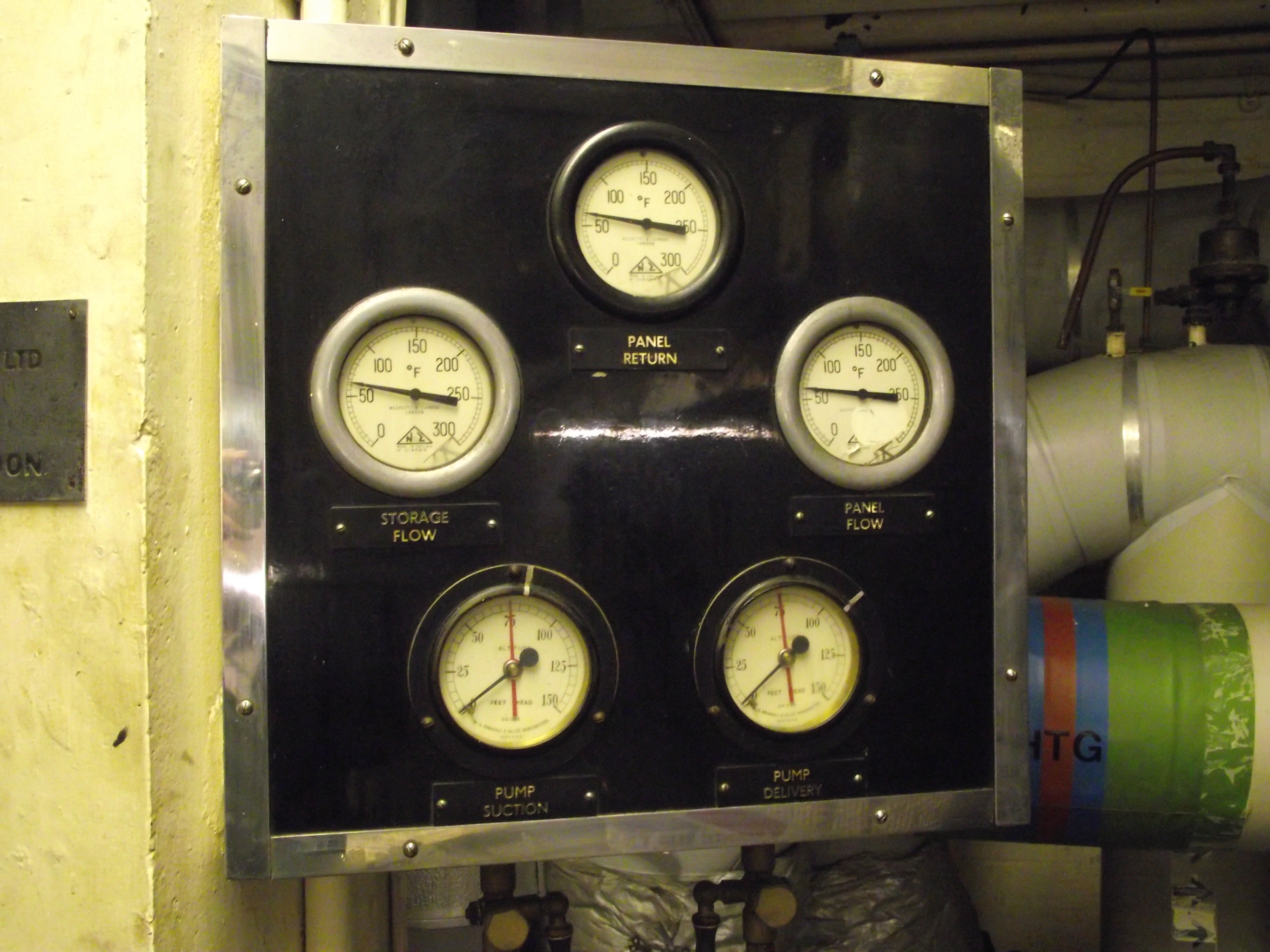 Instrument Panel |
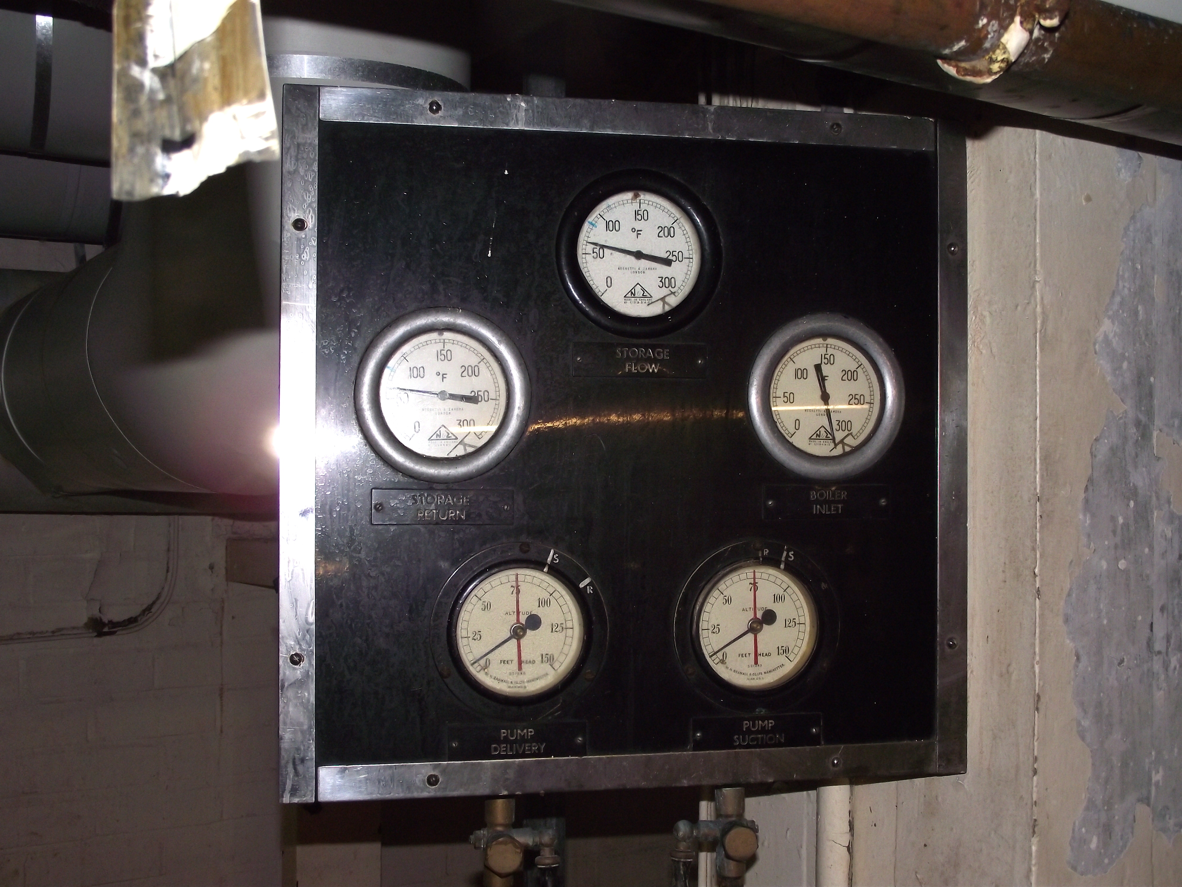 Instrument Panel |
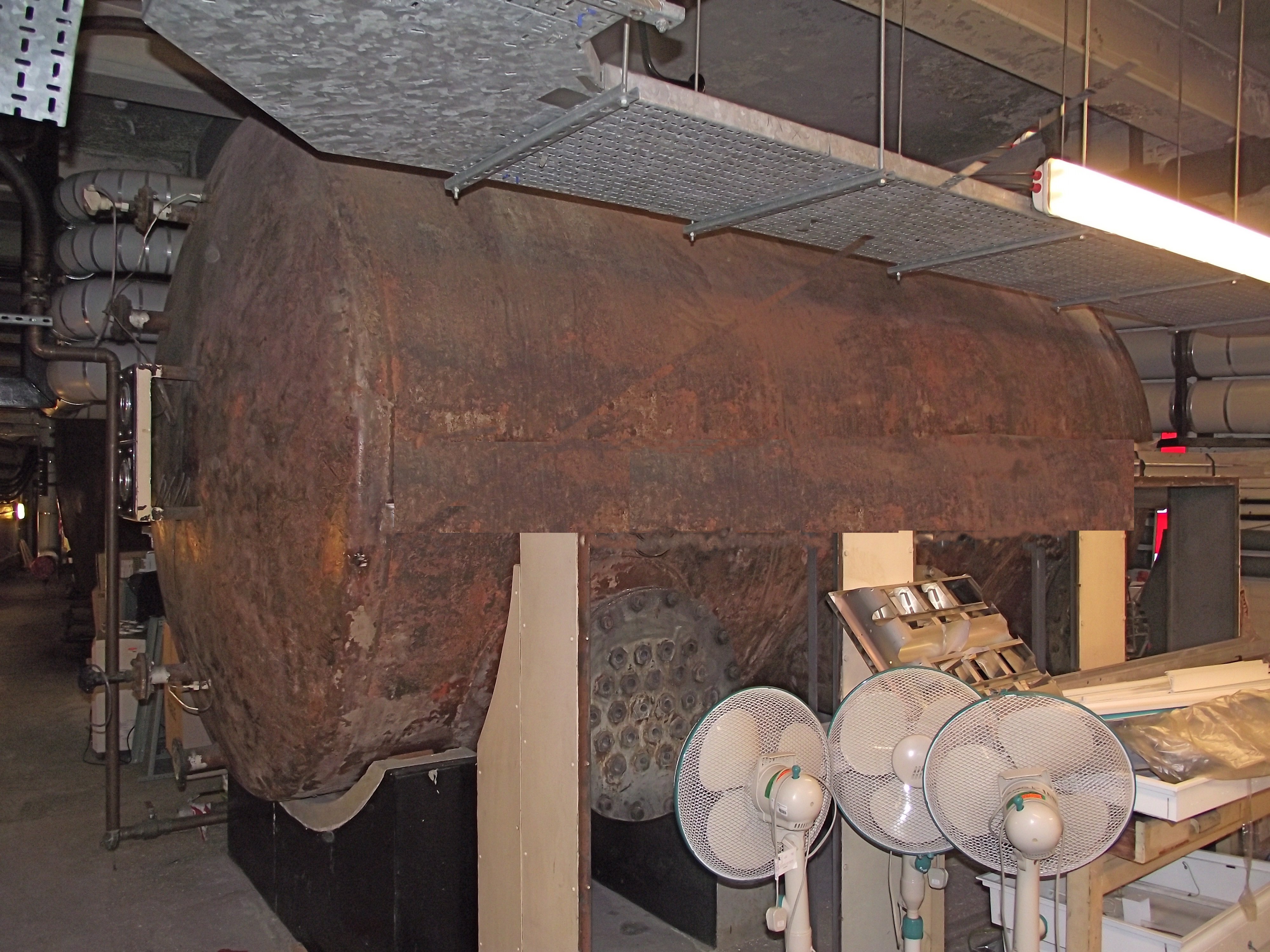
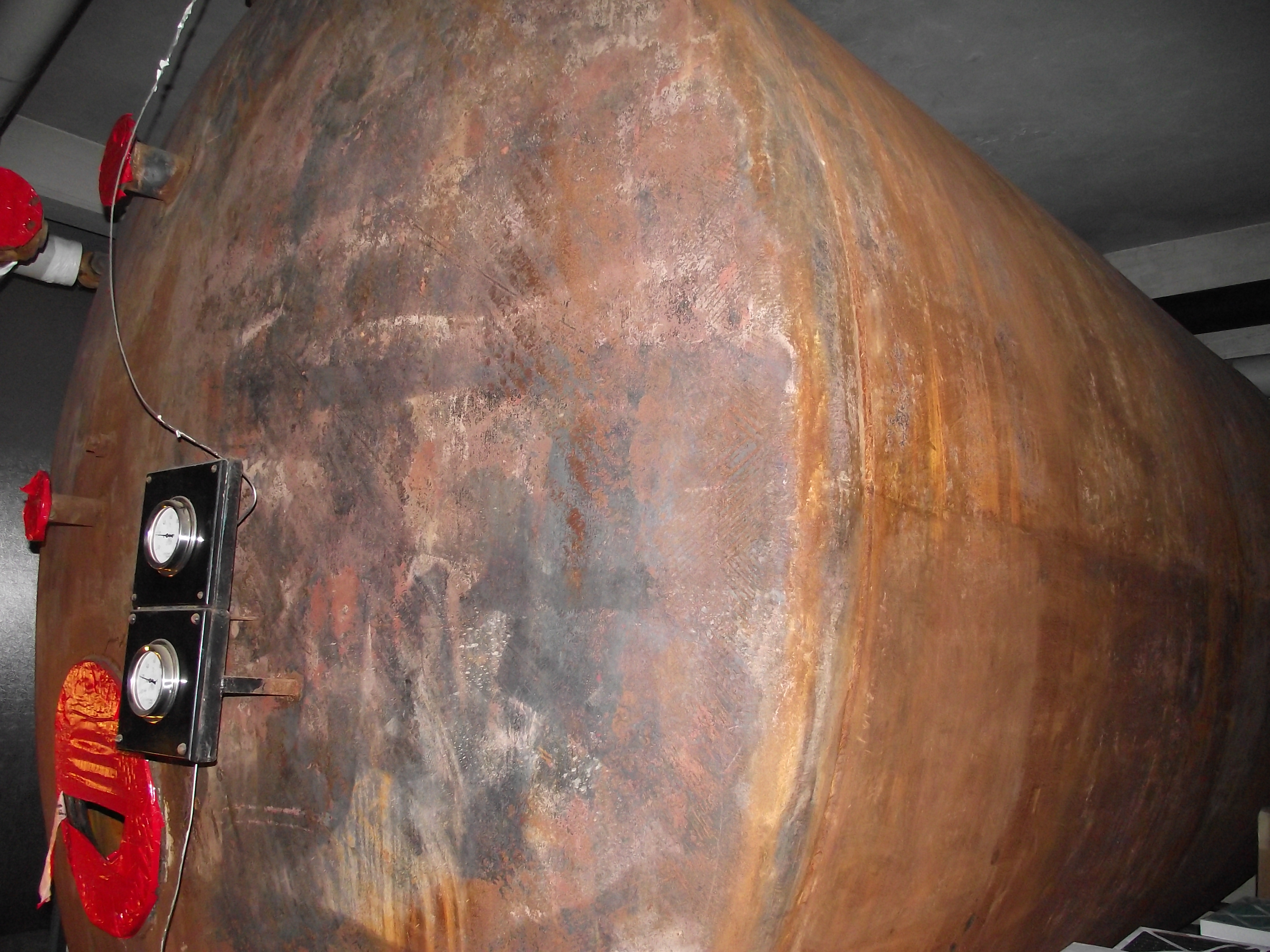 A restricted view of one 9000 gallon thermal storage vessel stripped of its thermal insulation |
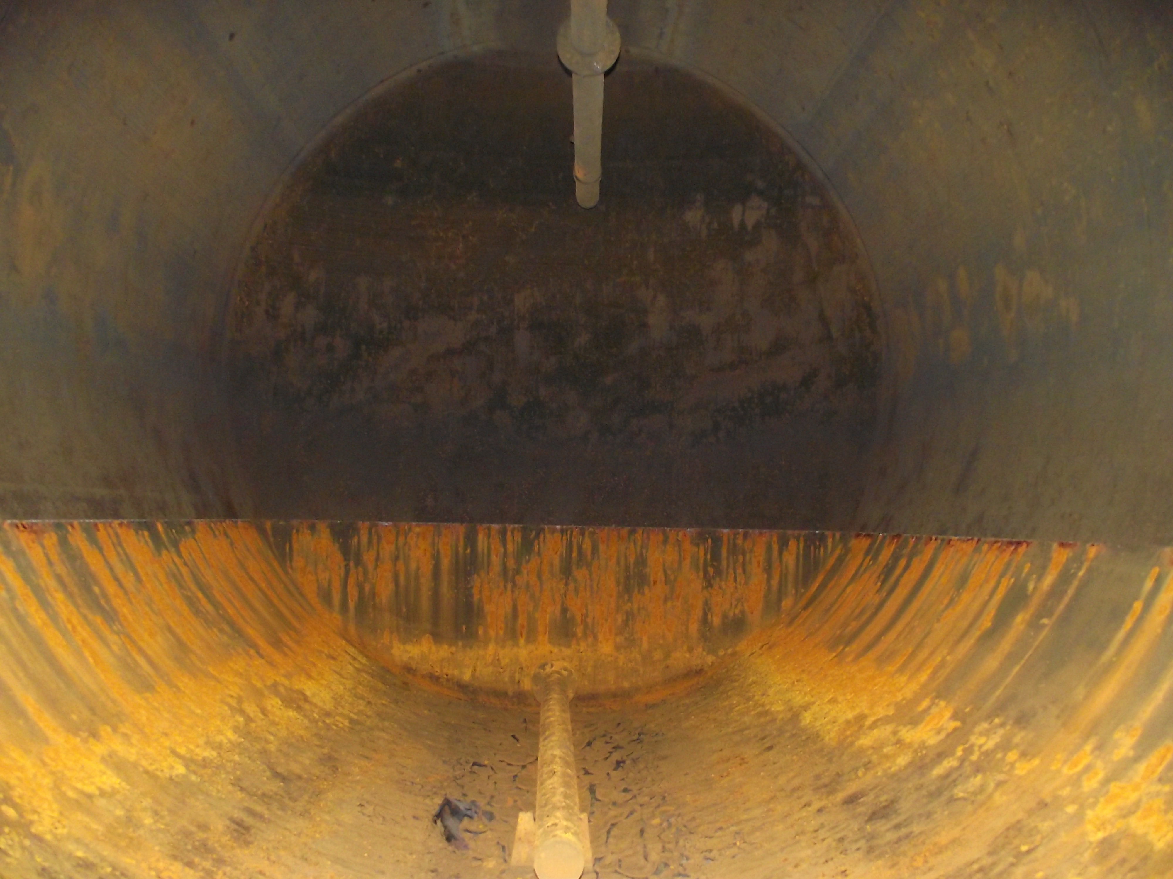 Internal view of one storage vessel showing its top & bottom sparge pipes, fitted to minimize the mixing of hot and cold water within the vessel. |
| The
heating distribution system was designed as an up-feed
arrangement using flow & return riser pipework
based on the reverse return principle to provide a
self balancing system. This method of designing
pipework circuitry to minimize the water flow
balancing was a relatively new method developed during
the 1930’s. The up-feed pipework risers were
concealed in vertical wall ducts enclosed on external
columns rising through the 4 floor levels. |
|
Three
duty/standby pump sets were fitted to distribute
heat to the various items of equipment.
Circuit
1)
Primary flow and
return to both electrode boilers
and thermal storage vessels. 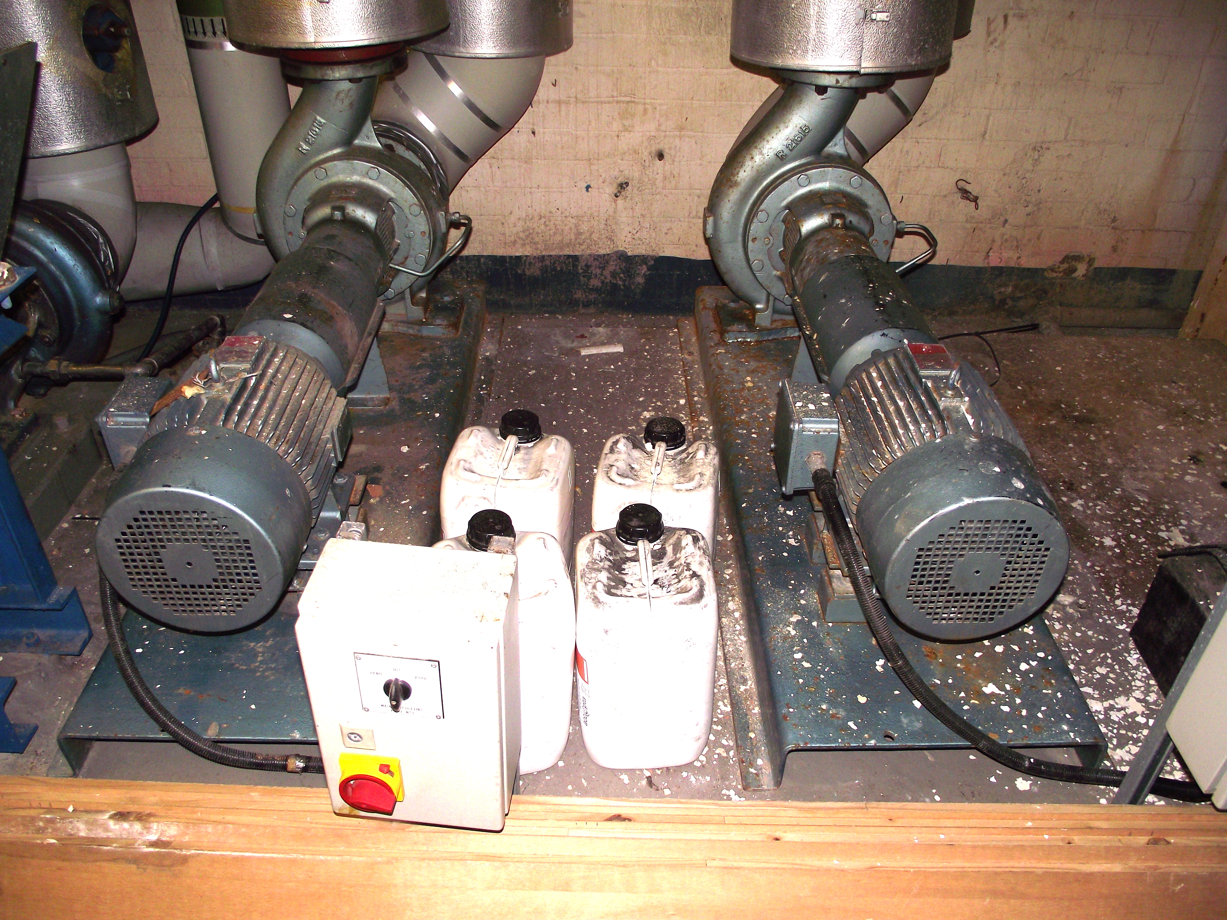 Circuit
2) Secondary
flow and return to mixed / blended temperature
circuits serving the embedded panel system. 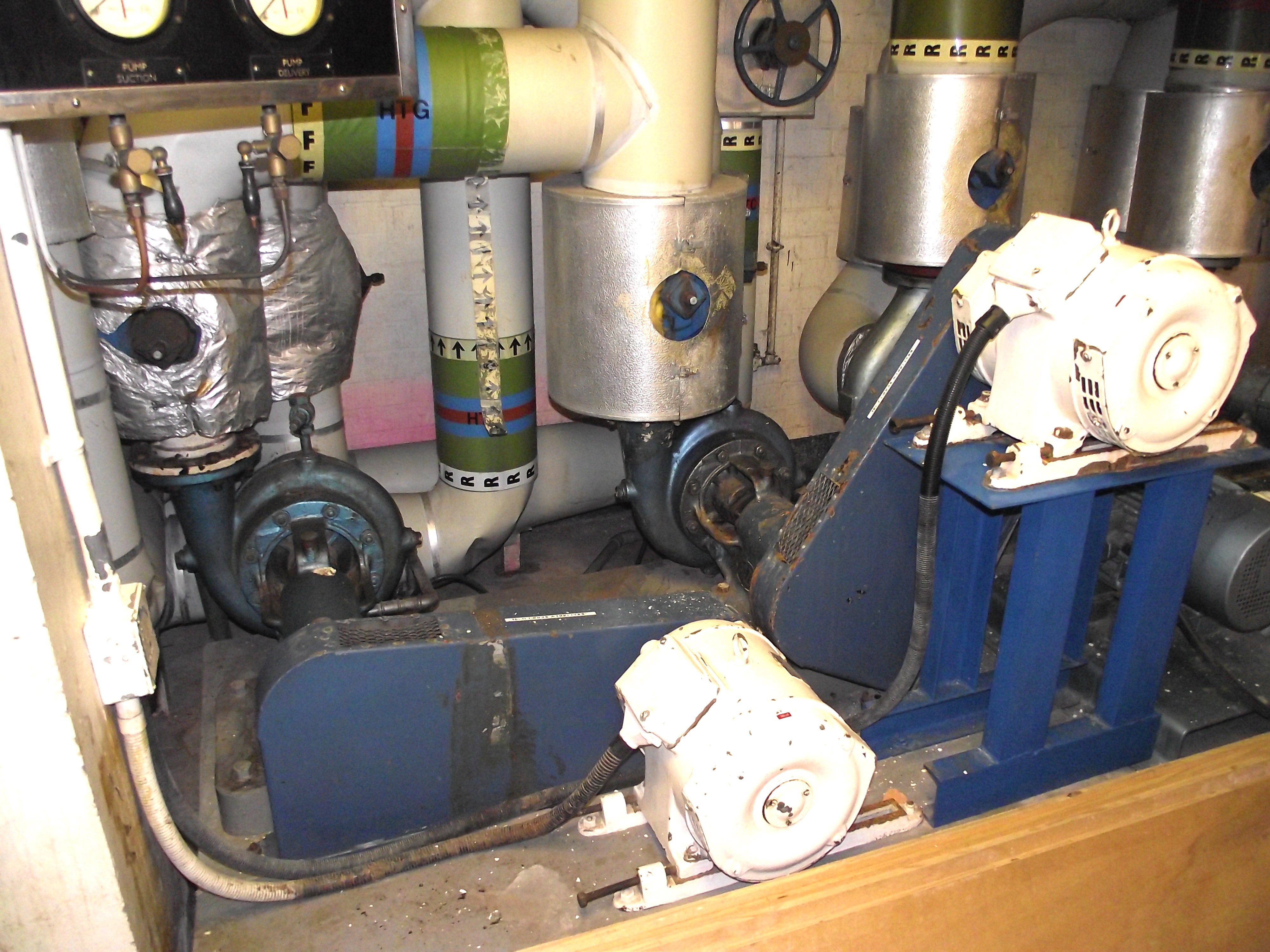 Circuit
3) Secondary
flow and return to constant temperature circuits
serving the three ventilation plants. 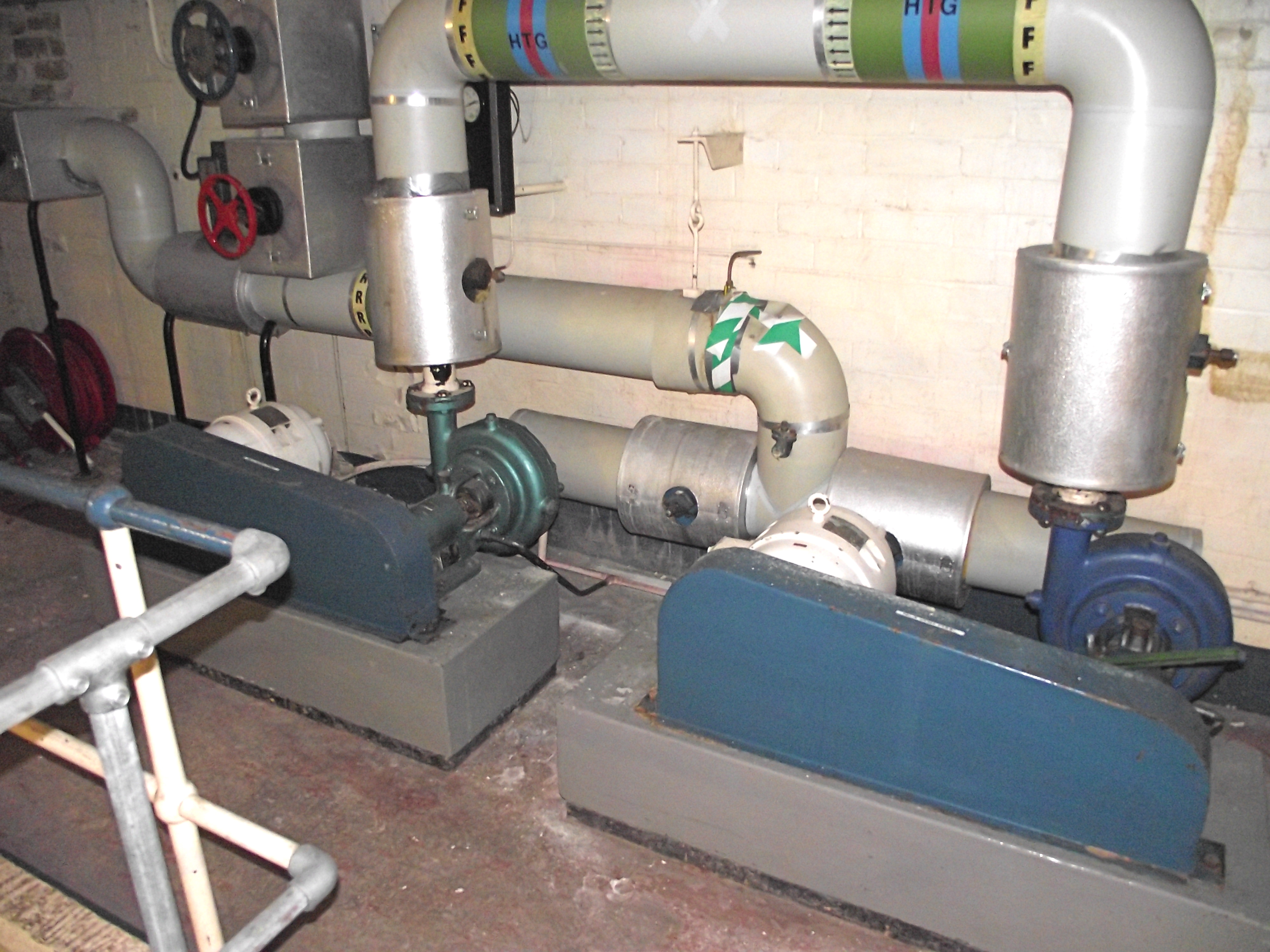 |
|
Ventilation
The
building has three separate ventilation plants
supplying filtered and heated air, to the Conference
Hall; Council Chamber; Ground Floor Cash / Rents
Offices. The ventilation plants have their own
independent Supply and Extract ventilation systems
with a constant temperature pipework distribution
circuit from the thermal storage vessels. Each
supply ventilation plant has been fitted with a new
air handling unit, which incorporates run-round heat
recovery coils.
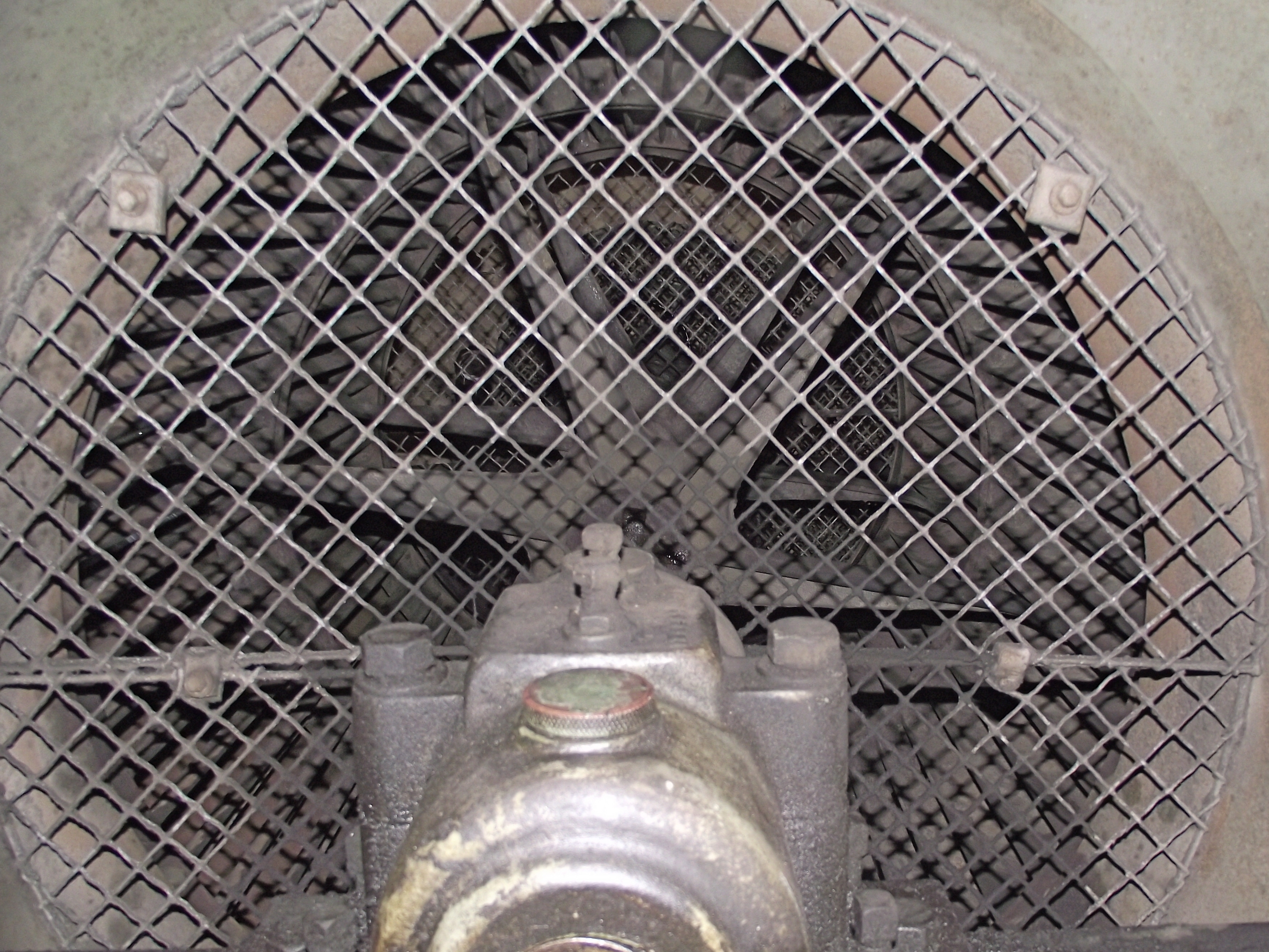
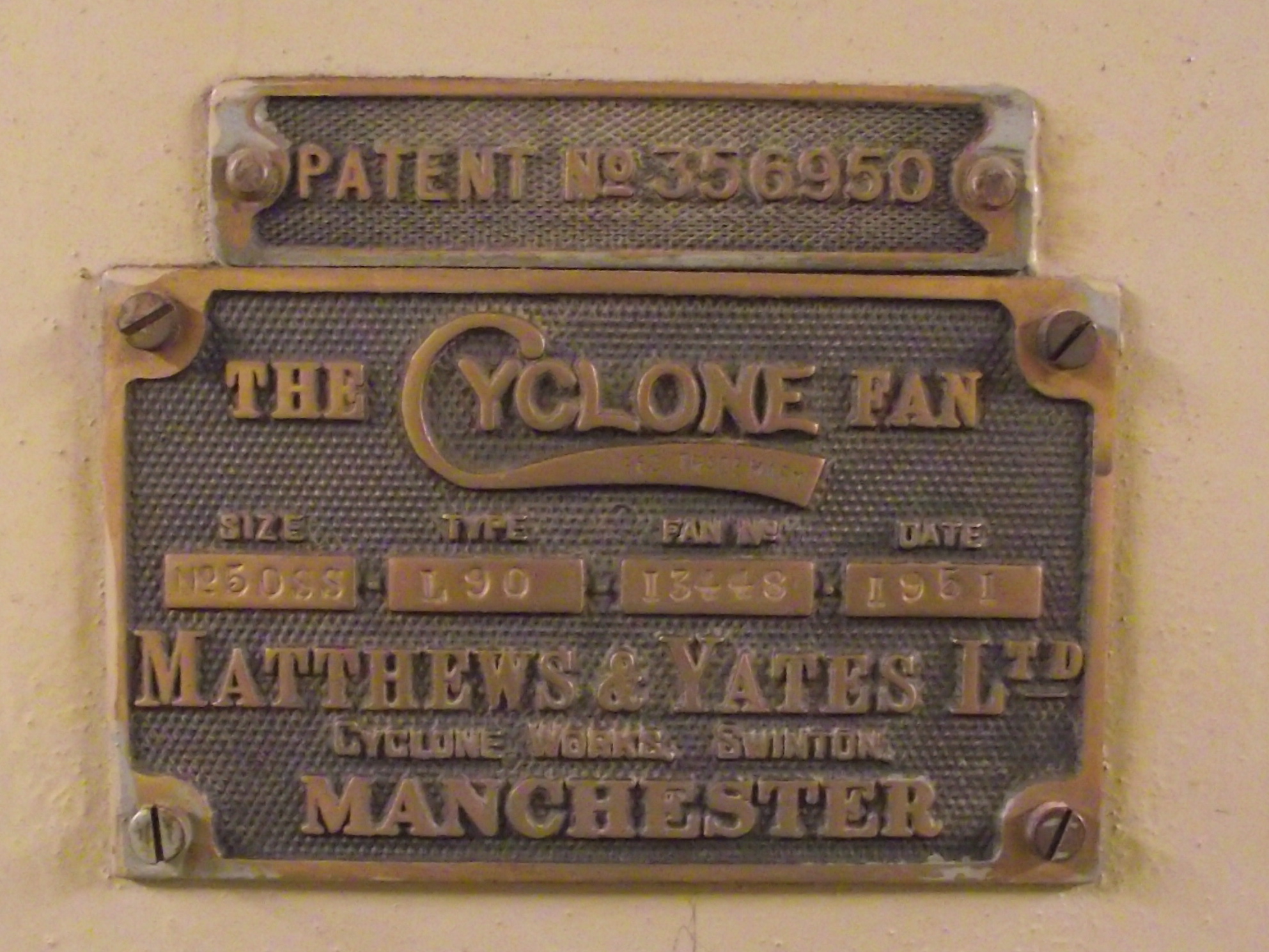
 Conference Hall Supply Air Handling Unit 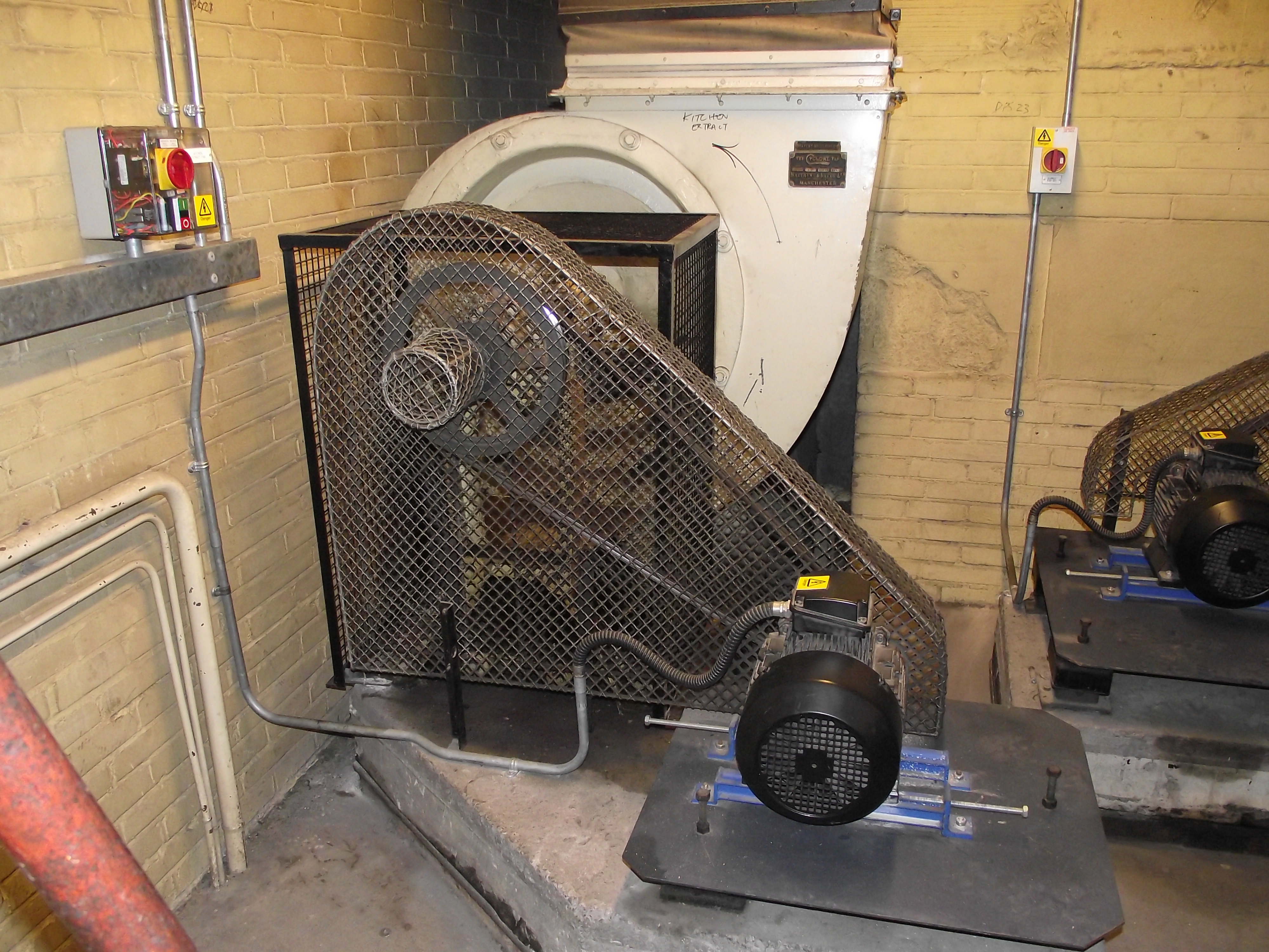 Conference Hall Extract Fan 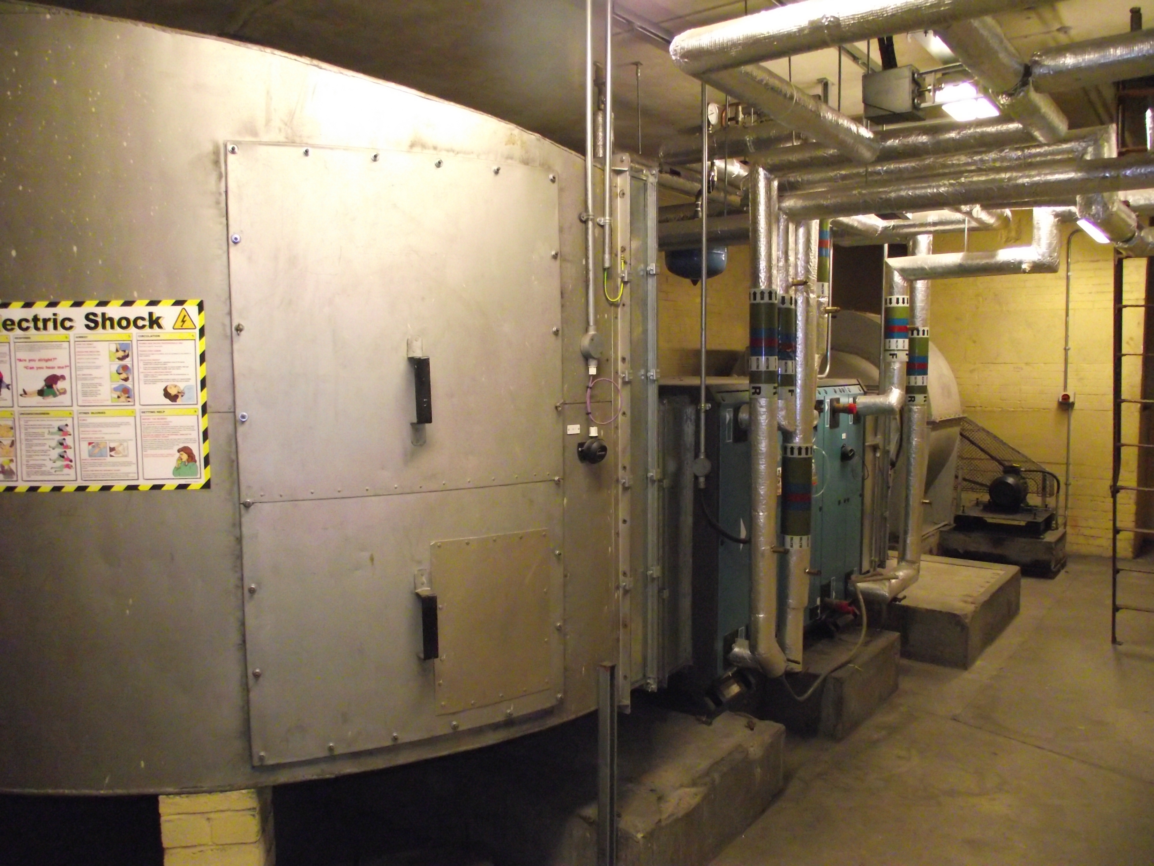 Council Chamber Supply Air Handling Unit 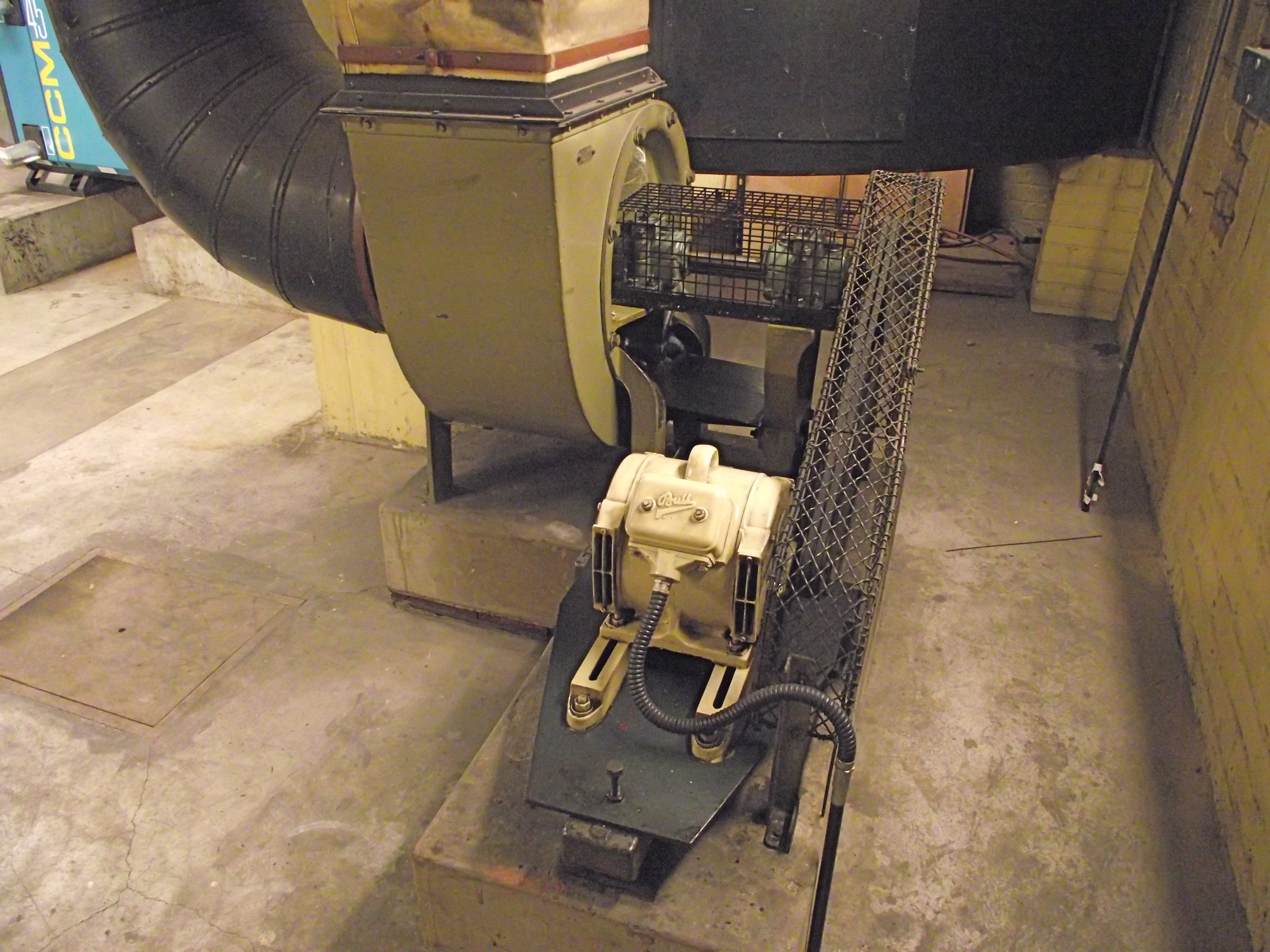 Council Chamber Extract Fan 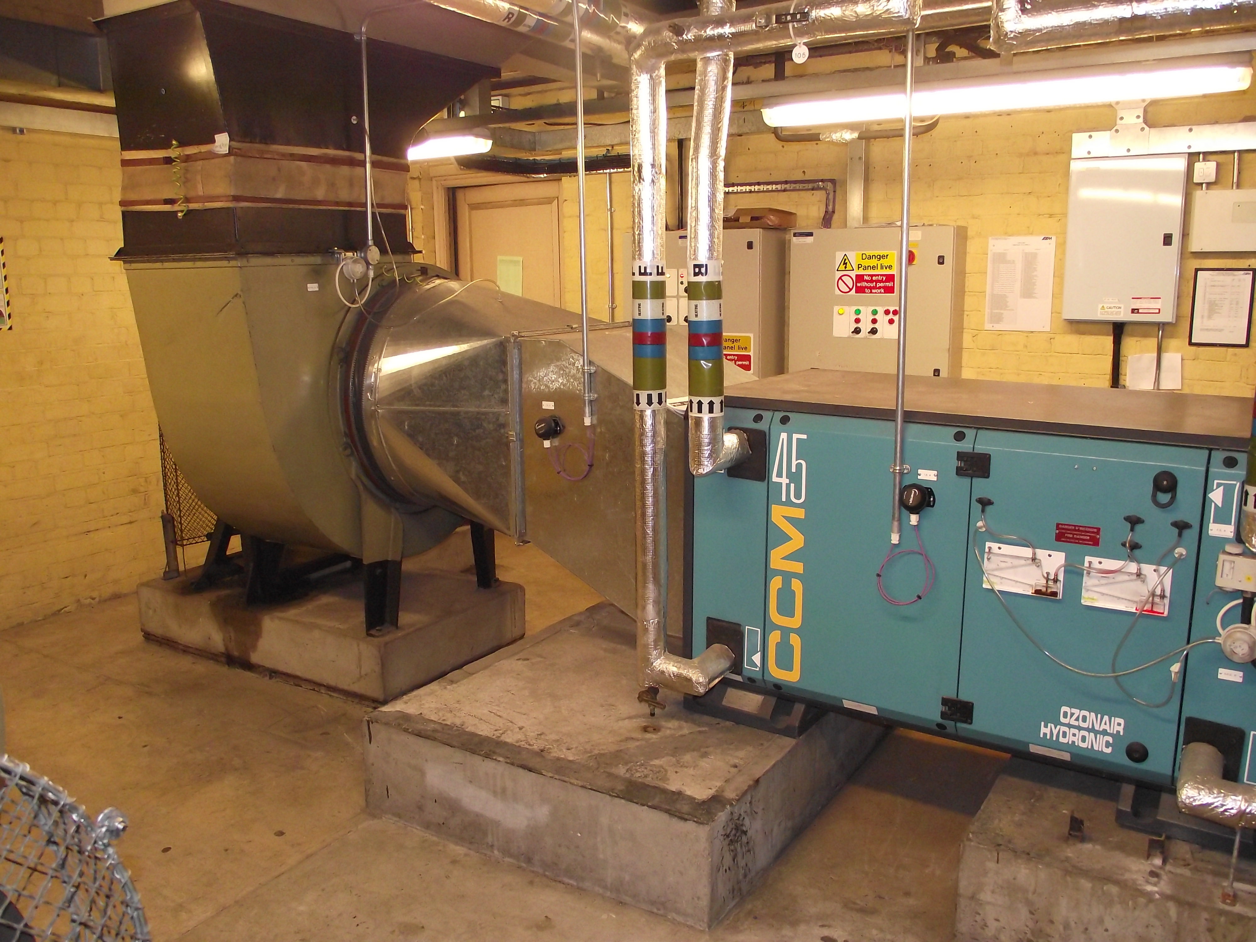 Ground Floor Offices Supply Air Handling Unit 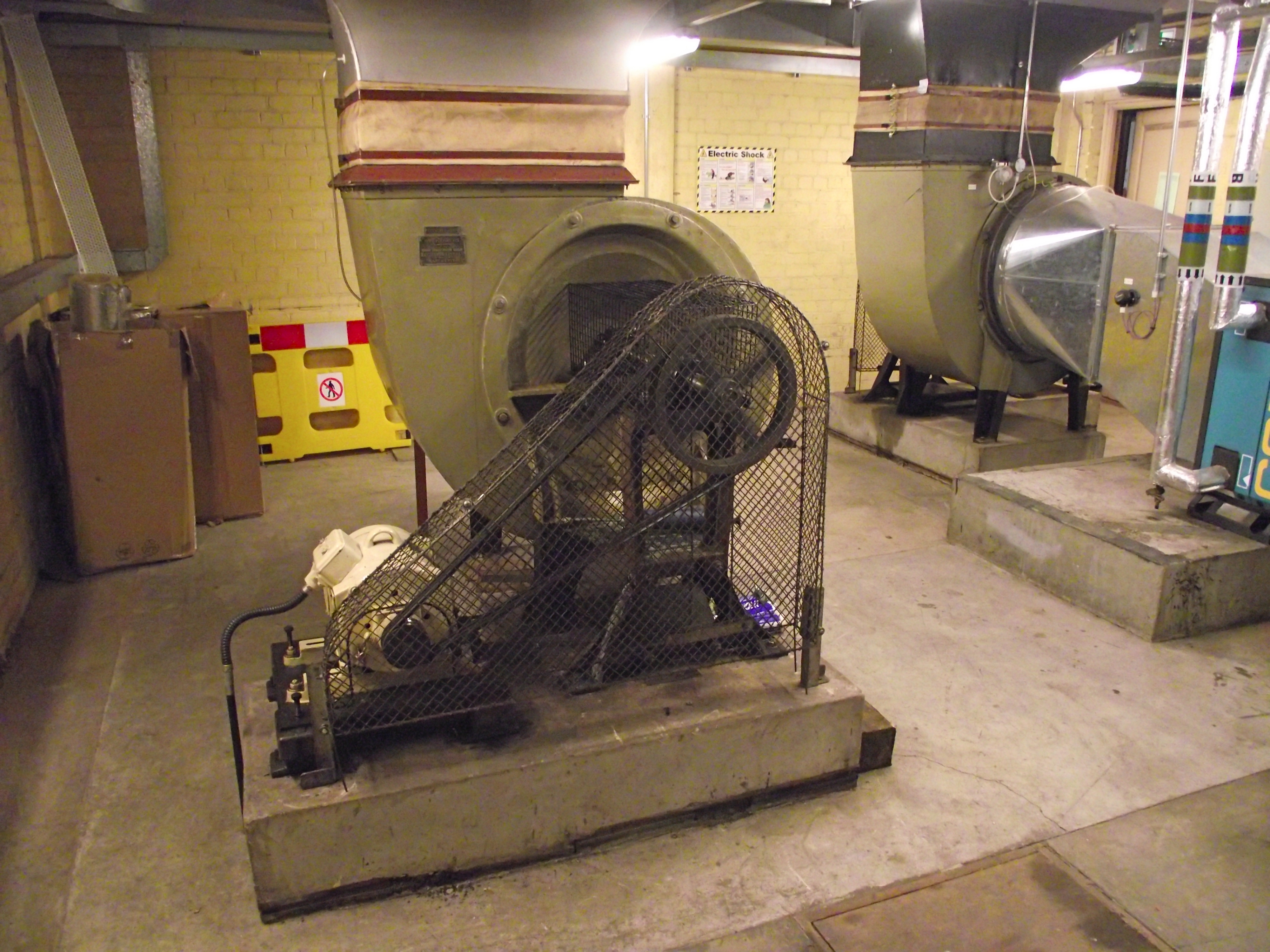 Ground Floor Offices Extract Fan The
original supply and extract belt driven forward
curved centrifugal fans manufactured by Matthews
& Yates in 1951 are still in operation. They
have all been fitted with replacement belts and
motors as became necessary due to wear and tear
from over 60 years of use.
|
|
Domestic
Hot Water Supply
The
domestic hot water was also generated by off-peak
electricity that heated a single storage vessel.
This storage vessel was of a smaller size but
similar shape to the heating vessels and installed
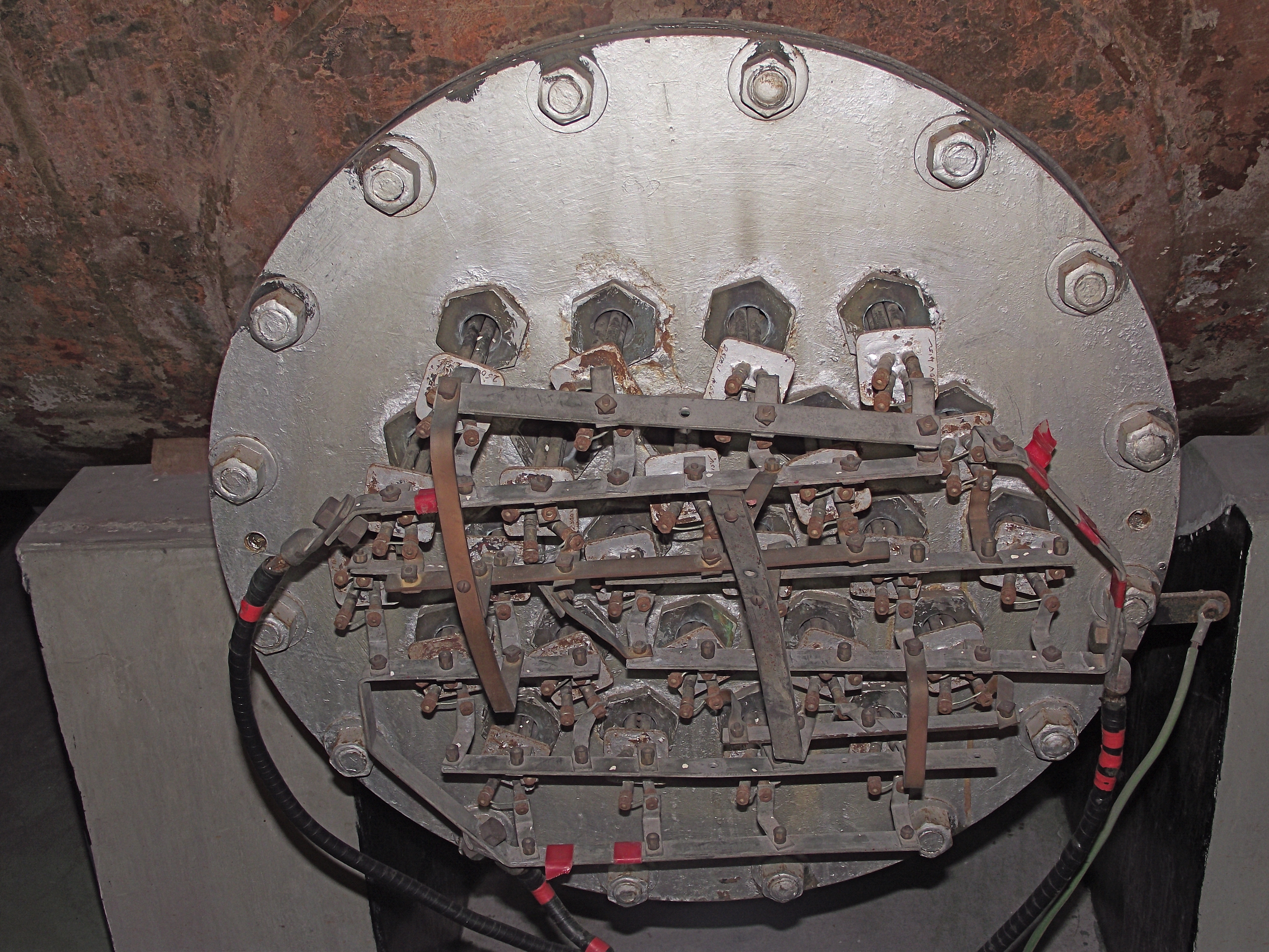
adjacent to them. Three banks of electric immersion
heaters were fitted in the vessel with each bank of
heaters arranged in a group of three single phase
circuits to balance the electrical heating load.
The storage vessel is fitted with internal sparge pipes to minimize the mixing of hot and cold water within the vessel.
A secondary pumped circulation pipework circuit fed the various sanitaryware and kitchen equipment throughout the building. |
JUNE 2012