|
THE
PERKINS FAMILY |
|
A short
history about FOUR
GENERATIONS
|
Perkins Heating Systems in South Wales
Researched, written
and prepared by
F J Ferris for the Heritage Group of the
CIBSE October 2002 - 2009
with acknowledgements to,
The Institution of Civil Engineers,
Wiltshire Record Office
Baker Perkins Historical Society
Birmingham Library Patents Office,
British Library
The Institution of Mechanical Engineers
for their assistance and information.
 |
THE PERKINS FAMILY |
|

FOUR GENERATIONS OF ENGINEERS
|
This is a short article about the Perkins family. Four generations of the family, all engineers, inventors, patentees and authors which spanned over 170 years. Each family member was directly involved with heating and ventilating of buildings. They also all carried out pioneering research into the production of artificial cold. |

 |
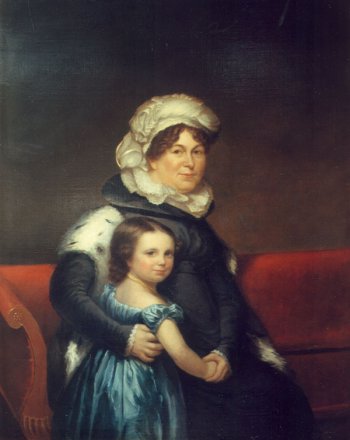 Portrait of Hannah Perkins with her grandaughter Maria Louisa Bacon painted by the artist Chester Harding |
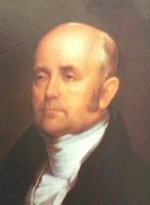
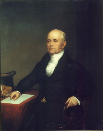 Portrait of Jacob aged about 58 painted by the artist Chester Harding c.1824 |
|
The list of his Patents is impressive in their engineering diversity. Number 4400
11th October 1819
Machinery and implements applicable to ornamental turning and
engraving. Number 4470
3rd June 1820
Construction of fixed and portable pumps Number 3732
10th
December 1822 Steam
engines Number 4792
17th May 1823
Heating, boiling or evaporating by the steam
of fluids in pans, boilers or other vessels Number 4800
5th June 1823
Steam engines Number 4870
20th November 1823
Construction of the furnace of steam boilers
Number 4952
15th May 1824
Throwing shells and other projectiles Number 4998 9th August 1824 Propelling vessels Number 5237
11th August 1825 Construction
of
bedsteads, sofas and
other similar articles Number 5477
22nd March 1827 Construction
of
steam engines Number 5806
2nd July 1829
Machinery for propelling steam engines Number 6128 2nd July 1831 Generating steam Number 6154
27th August 1831
Generating steam; applicable to evaporating
and boiling fluids for certain purposes Number 6275
9th June 1832 Blowing
and exhausting air; applicable to various purposes Number 6336
20th November 1832
Preserving copper in certain cases from the
oxidation caused by heat Number 6662
14th August
1834
Apparatus and means for producing ice,
cooling fluids Number
7059 12th
April 1836
Steam engines; generating
steam; evaporating and boiling fluids for certain
purposes Number 7114
13th June 1836
Apparatus for cooking Number 7242
3rd December 1836
Steam engines; furnaces; and boilers, partly
applicable to other purposes |
For more information about Jacob Perkins
his ancestors and descendants visit internet website
www.bphs.net
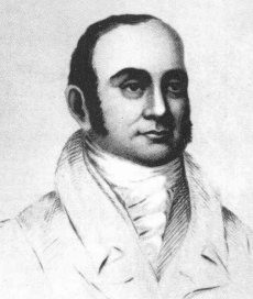
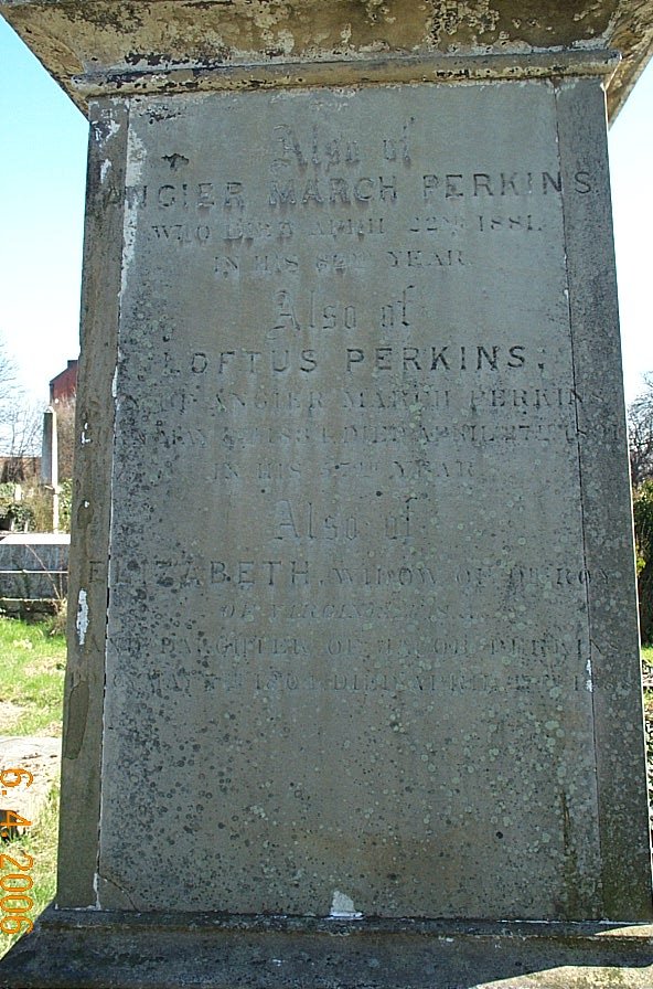
ngier
March Perkins
(1799 - 1881)
engineer, inventor, author and patentee, was named after
his uncle Angier March and the second surviving son of
Jacob and Hannah Greenleaf. Born in Newburyport,
Massachusetts USA on the 21st
August 1799. He sailed for England and arrived in
December 1821, and thereafter for some time was
associated with his father in perfecting his method of
engraving bank-notes, and also of using steam under very
high pressure. Following the subject of high pressure
steam he developed and patented a method of warming
buildings by means of circulating hot water through
small diameter pipes in a sealed system. The first
building to be heated by this type of system was in the
horticultural hot-houses at the house of John Horsley
Palmer (the then governor of the Bank of England) in
Fulham London in 1832. This method of heating came into
extensive use and was the foundation of a large business
carried out first in Harpur Street, which then moved
into Francis Street and finally into Seaford Street,
Grays End Road. He inherited much of his father’s
talents for inventions and like his father before
him he took out many patents between the years 1831
and 1864. BP 6146, 8311 and 8804 all relate to the
high pressure hot water method of heating and
subsequent improvements.
His patent in 1843 for the manufacture of and
melting of iron by the use of superheated steam was
remarkable insomuch as it evidently contained in it
the ideas of the subsequent discoveries relating
to the conversion of iron into steel, and the
elimination of phosphorus and sulphur from the iron. His attention to detail combined with his inventive powers rendered a great service to the mechanical world. Few of his inventions were the subject of patents, but the left and right hand thread screwed joint which was patented by him, has to be admitted to have been essential in its use for hydraulic work. As a method of joining two pipes together and forming a sealed joint capable of bearing the same pressure as the pipe itself shows it to be both simple and effective. In later years the system of circulating water in a sealed system, heated up to 2000 psi pressure was applied to the heating of baker’s ovens. This method was extensively adopted, as it possessed the advantage of being easily regulated. It was patented in 1851 BP 13509 and was later much improved. He was
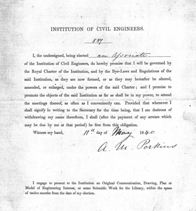
elected the 587th
member as an Associate of
the Institution of Civil Engineers on the 5th
May 1840. He married Julia Georgiana Brown in 1831 and they had four children, Angier Greenleaf, Loftus, an unknown daughter and Louisa Jane. In the census of 1881 he is recorded as living in Hampstead London with his son Loftus and his wife Emily, and their two children Loftus Patton jnr. and Ludlow Patton. Angier March died on the 22nd April 1881 in Hampstead London at the age of 81 and is buried in Kensal Green Cemetery London. |
The list of his Patents
Number
6146 30th
July 1831
Apparatus for heating air in
buildings Number 8311
16th December 1839
Apparatus for transmitting heat by
circulating water Number 8804
21st January
1841
Apparatus for heating by the circulation of
hot water; construction of pipes for such and
other purposes Number 9664 16th March 1843 Manufacture and melting of iron; applicable for evaporating fluids, and heating metals Number
10778
21st July 1845
Apparatus for heating air in buildings Number 13492 5th
February 1851 Railway axles and
boxes Number 13509
11th February
1851 Constructing
and heating ovens. Number 2755 6th December 1855 Apparatus for Generating Steam Number
2757 6th December
1855 Warming buildings and
apartments by hot
water Number
954 29th April
1858
High Pressure Steam Engines Number
2124 21st September 1858
Surface Condensors Number
2017 21st August
1860 Apparatus for distilling
sea &
other
water Number
342 9th February
1862 Warming Rooms and Buildings Number 2253
15th September 1864 Constructing ovens
and applying
wrought iron
tubular apparatus for circulating
hot water to heat the same |
oftus
Perkins (1834 - 1891)
engineer, author, inventor and patentee was born
on the 8th May
1834 in Great Corham Street, Russell
Square, London. At a very early age he entered his
fathers manufactory and during 1853 – 1854 he practised
on his own account as an engineer in New York. Returning to England he
remained with his father for 8 years until 1862 working
on the steam gun and other inventions. From 1862 until
1866 he was in business on his own in Hamburg and Berlin
designing and installing many systems for warming
buildings in various parts of the continent. Returning
to England in 1866 he entered into partnership with his
father and worked on the design and construction of
steam engines, boilers and especially in developing the
use of high pressure steam as applied to steam engines.
The partnership continued until his father’s death in
1881. He inherited much of the inventive capacity of his father and grandfather, and from 1859 onwards took out a very large number of patents. The main subjects to which he directed his activities were the use of high pressure steam as a motive power, and the production of artificial cold.
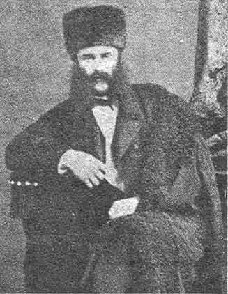
"He was a man with brown eyes, well proportioned in build and a great chemist and engineer. He had a large moustache and Dundreary whiskers, who always wore a double-breasted blue suit, and in the Works, a peaked cap with silk oak leaves around. In the winter he used to wear a Canadian fur cap. He came into the Works one Sunday morning dressed in white flannels with a white peaked yachting cap. He smoked 13 ounces of tobacco a week - he always carried a pouch with 4 ounces of tobacco in it. His type of tobacco was "Branksome's Light Virginia". In conjunction with his friend Dr Williamson he took out three patents in 1859 and 1860 for surface condensers, steam engines and boilers. In one of which he says “Our chief object is to employ steam of very high pressure; as for example of 500 psi. or more or less and to expand this steam several times, and then condense it so as to obtain a great amount of power from a small quantity of steam”. He devoted many years of his life to this subject. His labours in this subject are shown in two papers read before the Institution of Mechanical Engineers in 1861 and 1877 and published in the “Proceedings” for those years. Among his many inventions is his patent in 1867 for water meters, and one in 1868 for wrought iron metal wheels, the spokes of which consisted of hollow bars or tubes screwed into the nave or tyre. A large number of gun carriage wheels were constructed using this principle for the Government, and though they stood the most severest of tests nothing more was heard of this invention. Another
of his inventions described in 1891 in Fletcher's book
"Steam Engines on Common Roads" says, His yacht Anthracite, constructed in 1880 was fitted with engines working with steam at a pressure of 500 psi. and it is probably the smallest ship of that time ever to have crossed the Atlantic steaming the entire distance. The Perkins engine company published a number of reports upon her performance, drawn up respectively by Sir Frederick Bramwell, by a committee of officers of the U.S. Navy and by Sir Frederick Bramwell and Mr William Rich conjointly. He continued with the experiments which had occupied the attentions of his father and grandfather which was the production of artificial cold which resulted in the “Arktos” a cold chamber suitable for preserving meat and other items of food. It was based on the separation of ammonia gas from the water in which it is dissolved, the liquefaction of the gas, and the subsequent revapourisation of the ammonia, with the reabsorption of the gas by the water. This was his last great work, and his unremitting attention to it inevitably caused a breakdown in his health. He
became a Member of the Institution of Mechanical
Engineers in 1861 followed by Membership of the
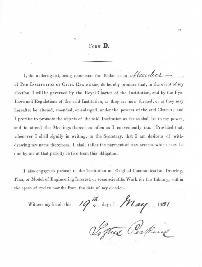
Institution of Civil Engineers in 1881. Loftus
died on 27th April 1891 at his home in 148
Abbey Road Kilburn London at the relatively young age of
57. Compared with both his father (82) and grandfather
(83), maybe, just maybe, his addiction to tobacco and
his heavy pipe smoking compounded by the stress of his
great work load contributed to his early death. His Will
was proved on the 28th May 1891 in the sum of £1829. A
very modest sum when considered against the inventions,
Patents and other business interests he achieved during
his working lifetime. He was survived by his wife Emily
and their two sons Loftus
Patton and Ludlow Patton. Both of
his sons worked in their fathers business which by then
had been made a limited company. It would appear that
after the death of their father and a lapse of several
years, some form of discord occured between the
company and the two brothers, as they both left the
firm to establish their own careers.
|
 A
description of Loftus written by his assistant Charles J
Hayward who worked with him on many of his experiments
says,
A
description of Loftus written by his assistant Charles J
Hayward who worked with him on many of his experiments
says,|
He
was a prolific
inventor and made
30 Patent applications between the years 1859 and 1879 |
|
The List of his Patents Number 1940 25th August 1859 Mills Number 2208 29th September 1859 Steam Boilers Number 2686 28th November 1859 Machinery for Propelling Vessels Number 2285 20th September 1860 Surface Condensors Number 2392 3rd October 1860 Steam engines Number 636 7th March 1865 Apparatus for heating and cooling atmospheric air other aeriform bodies and for heating ovens and for heating buildings Number 3050 29th October 1866 Improvements for actuating the valves of water meters and other meters, and of engines for obtaining motive power Number 1379 27th April 1868 Manufacture of wrought metal wheels Number 1381 27th April 1868 Tubular Steam boilers Number 2436 8th September 1870 Locking gear of the fore carriage of Wheeled vehicles Number 1508 24th May 1870 Connections for fire engine hoses and other pipes Number 1379 23rd May 1871 Wheels for traction engines Number 1822 12th July 1871 Steam Engines Number 2818 21st October 1871 Locomotive and traction engines Number 2819 21st October 1871 Marine and stationary engines Number 3845 18th December 1872 Locomotive engines Number 2616 3rd September 1872 Packing rings for pistons Number 224 20th January 1874 Steam-engines etc. Number 507 6th February 1877 Steam-engines and valves Number 2301 8th June 1878 Propellors for ships Number 5243 23rd December 1879 Wearing surfaces of steam and other engines |
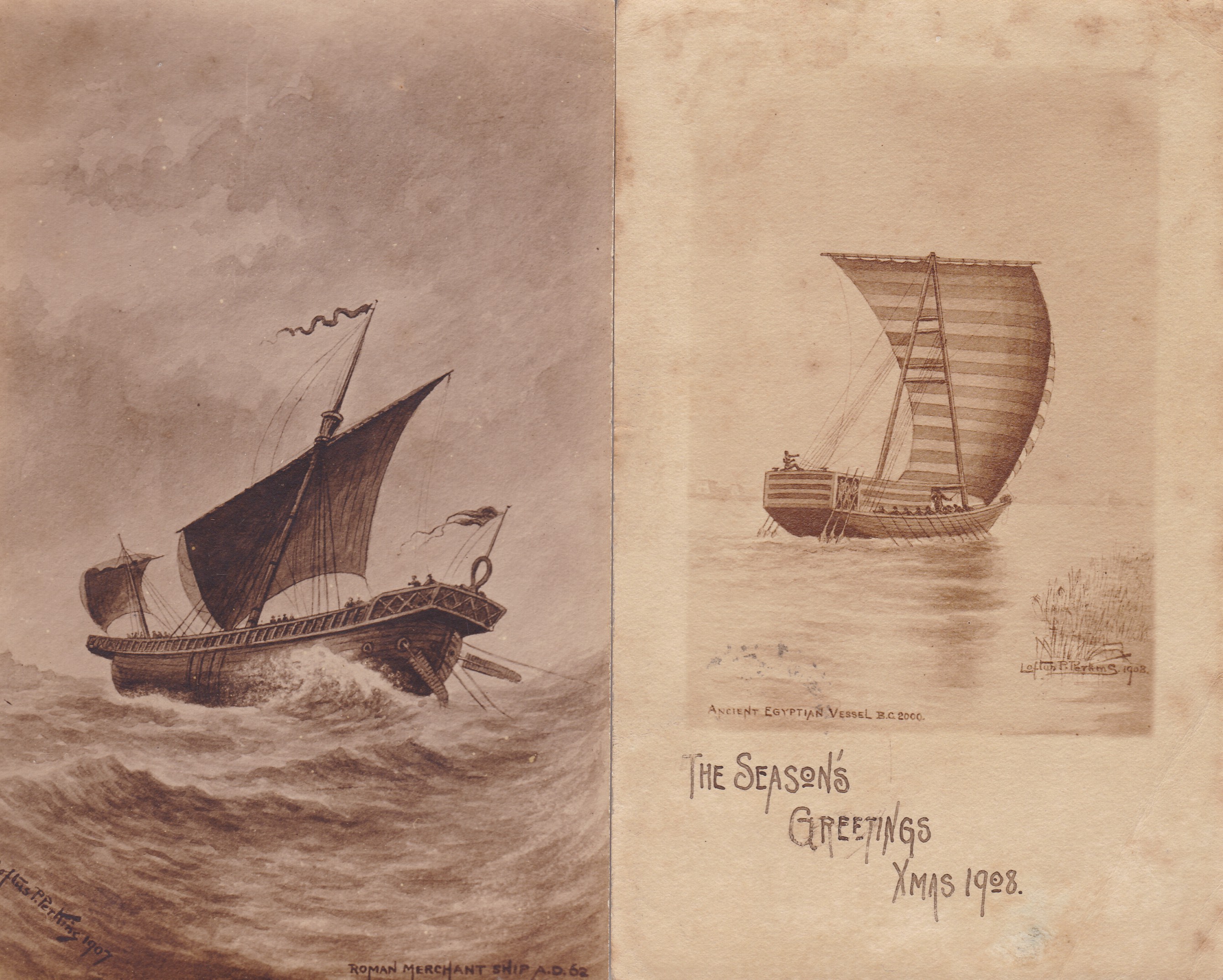
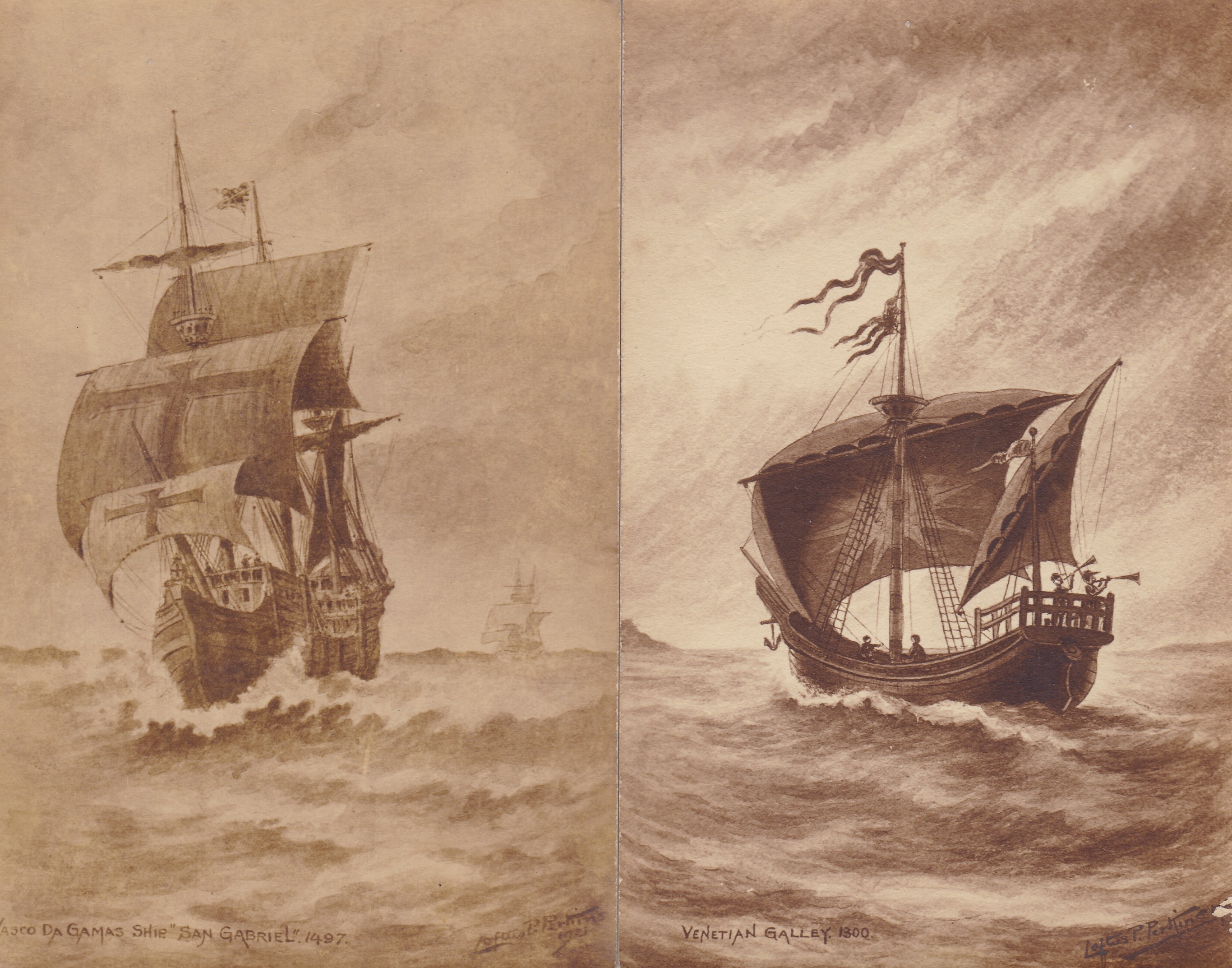
oftus Patton Perkins (1868 - 1940) the eldest son of Loftus was born in Kilburn London in 1868 and in his younger years followed the engineering path of his father working in his business. In the 1901 census Loftus then aged 33 years is recorded living with his wife Henrietta in Willesden London, and giving his occupation as Mechanical Engineer. By the time of the 1911 census their only child had died and he still gave his occupation as Mechanical Engineer. Loftus soon showed that he possessed another talent. In 1883 he prepared an advertisement extoling his ability as an artist who would undertake commissions for clients. Watercolour paintings have recently come to light which span the years 1907 to 1933. He became an accomplished artist as the watercolours shown below beautifully illustrate. The watercolours titled Thames Barges painted in 1926 and London Bridge painted in 1933, opens up a new line of research for the Group to determine how well he was known as an artist in that time period, and to establish also just how many other paintings by him still exist. Also to determine whether he no longer traded as a Mechanical Engineer. A selection of 9 postcards painted by Loftus between 1907 and 1934 has been acquired by the Group which shows his continuing dedication to watercolours. The theme for all these postcard paintings are maritime settings, which must have been his greatest interest. Four of these paintings are shown below.
Loftus Patton died in 1940 in London, aged 72 years. 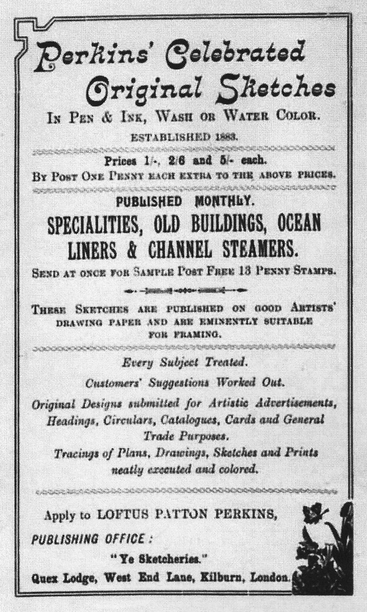 Copy of the watercolour painting kindly provided by James Buttram. 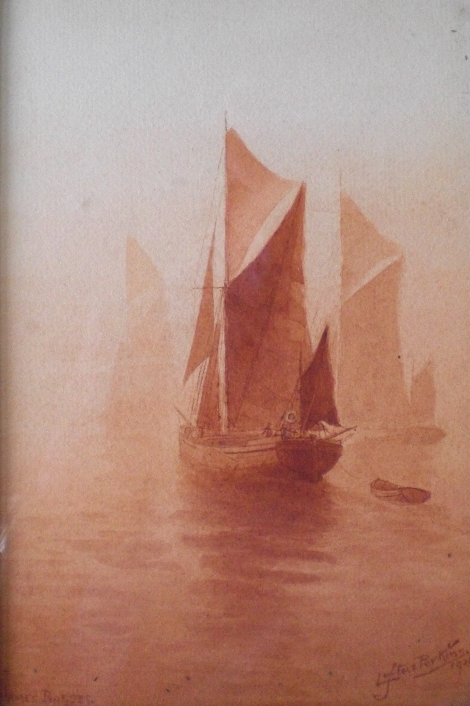 Copy of the watercolour painting kindly provided by Mike Alderson.
|
||||
udlow
Patton Perkins (1873 - 1928)
the second and youngest son of Loftus was born in
Kilburn London in 1873 and followed the engineering path
of his father working in his business, which by the time
of the death of his father had become a limited company. In the 1901 census Ludlow then aged 28 years is recorded as living at 21 Herbert Street, Moss Side, Manchester, giving his occupation as Mechanical Engineer. Coincidentally, residing at the same address is George F Buck. who was probably related to the William Edward Buck with whom Ludlow made the Patent application. He moved to Lancaster in the year 1902 having previously lived in Manchester where he was for a number of years associated with Hy Wallmark and Co Ltd and also with Joseph Adamson and Son, of Hyde in Cheshire, with whom he was interested in the high pressure stopped-end tube boiler. His speciality was steam at very high pressures and on this subject he was very authoritative. He was a director of the Lune Valley Engineering Company Ltd of Lancaster and later practised as a Consulting Engineer, devoting his time and energies to the development of refrigerating apparatus. In conjunction with William Edward Buck, Engineers of Carisbrooke, Battershall, Worcestershire they applied for and were granted British Patent No. 22272 dated 1892 titled "Improvements in devices for the diffusion of transference of heat” This Patent gave improvements to the basic Perkins tube which had previously been the subject of earlier patents taken out by his grandfather Angier M Perkins and great-grandfather Jacob Perkins dealing with hermetic single phase and two phase heating tubes. In 1907 he married and from the 1911 census can be found still living in Lancaster giving his occupation as Civil Engineer. They had no children.
He died
on 18th October 1928 at Lansdowne House, Regent Street,
Lancaster at the early age of 56 years. |
So with both sons Loftus Patton and Ludlow Patten having no children the
four generations of the Perkins family as Engineers finally came to a close.
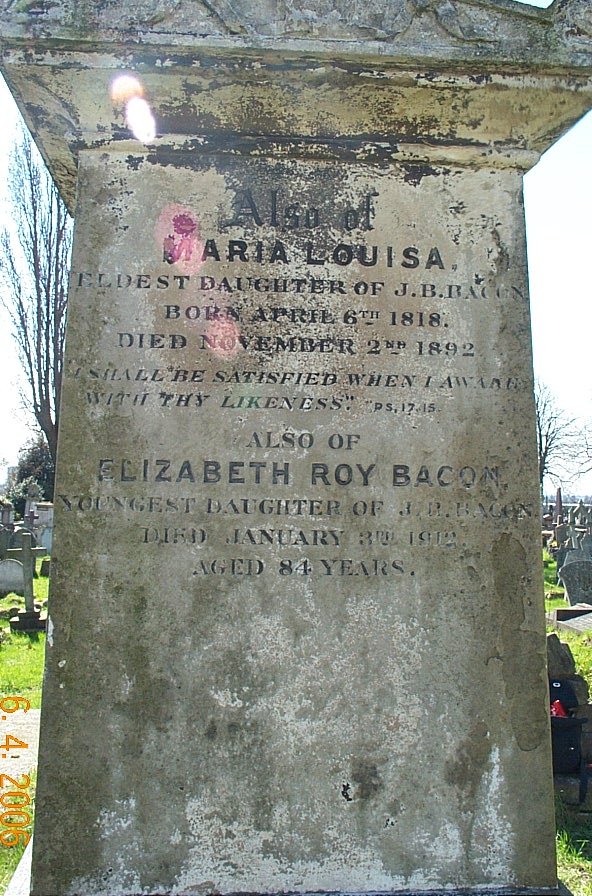
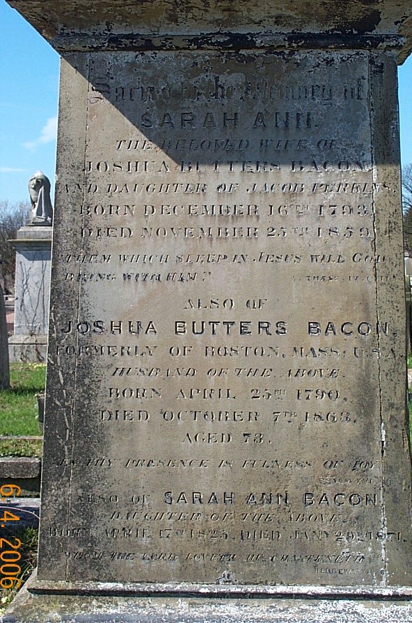
THE FAMILY'S FINAL RESTING PLACE
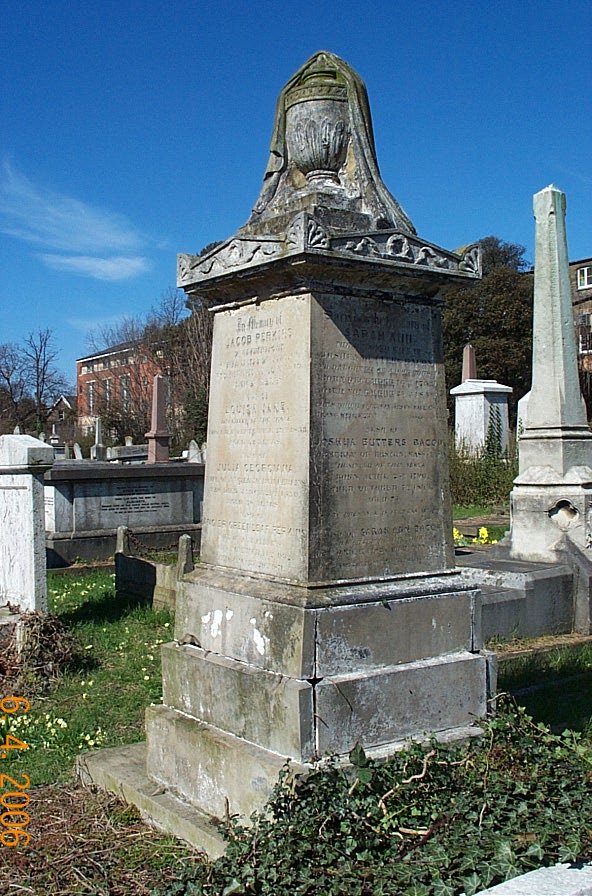
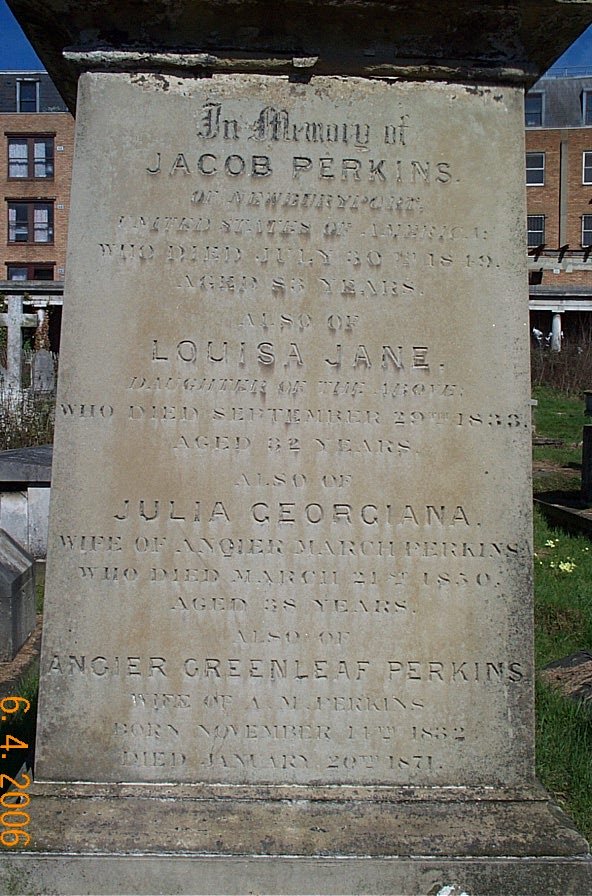
| The
first three generations of the family are all
buried in Kensal Green Cemetery London together
with their wives and other relatives, in an
imposing 3metre high grave marker monument,
surmounted by a draped urn. The people buried
there all died during the Victorian period. |
 |
 |
 |
 |
FEBRUARY 2004
|
The Perkins HPHW Heating System |
In the early 1800’s in pre-Victorian Britain central heating systems were slowly coming into fashion with steam or warm air always being used as the heating medium. The use of hot water as an alternative form of heating medium had not yet been considered.
In 1827 an American family named Perkins arrived in this country from Massachusetts USA. Jacob Perkins (1766 – 1849) and his son Angier March Perkins (1799 – 1881) both with their families. Jacob and Angier were Engineers and inventors who had already experimented with using hot water in sealed pipework systems to create heating systems capable of operating at high temperatures and pressures.
Angier Perkins continued this research with his experiments in England and by 1831 was ready to apply for a patent for his invention. His first British Patent 6146 dated 30th July 1831 was listed as “Apparatus for heating air in Buildings” which was to be the first of many. This new method of central heating was to circulate hot water through small diameter pipes at high temperatures and pressures. The Perkins Patent for their heating system was considered an ingenious and useful invention by the Privy Council who on the 10th March 1845 granted a five year extension of the Patent, from the termination of the present Patent.
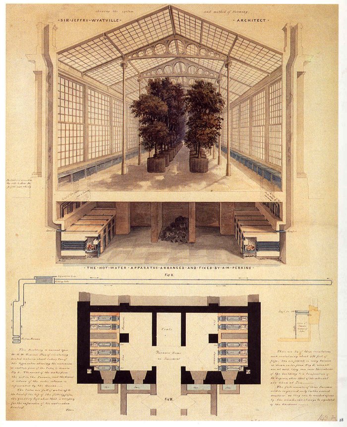
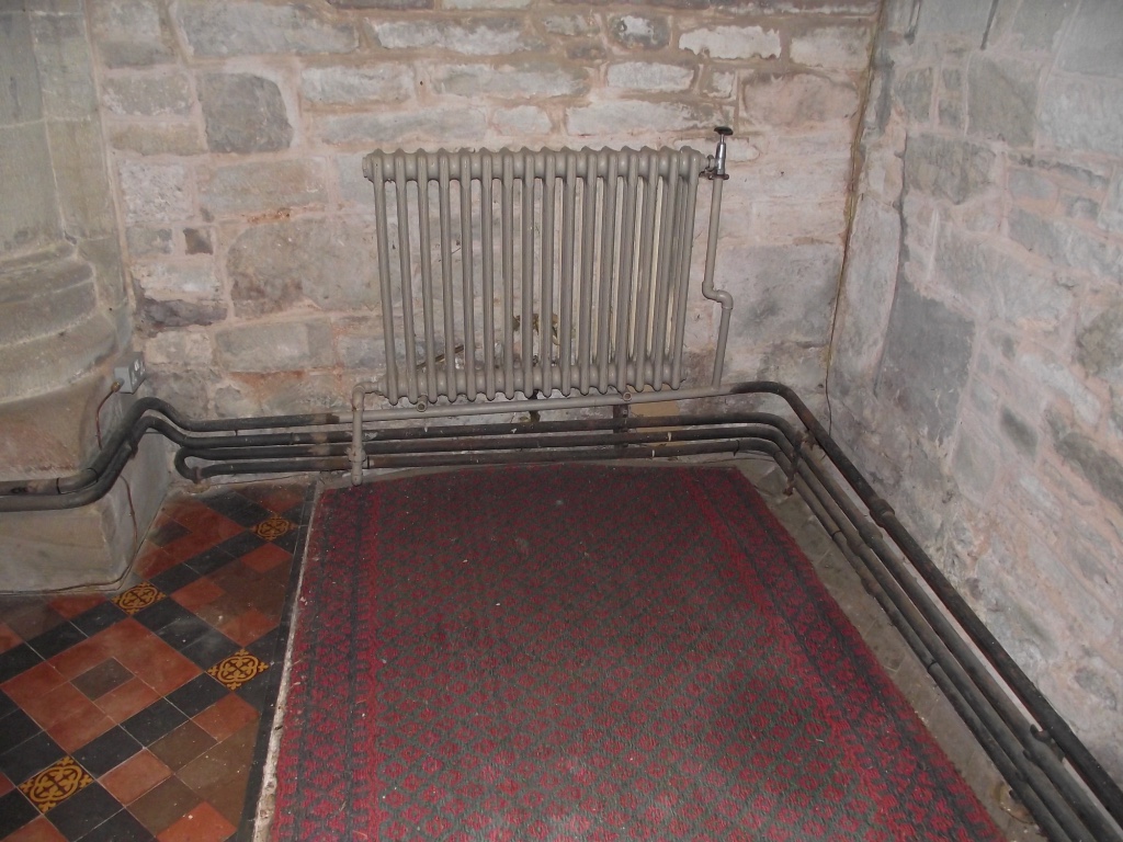
This new development in the heating of buildings quickly found favour with businesses and the aristocracy. During the 1830’s many of these systems, which had then become known as “The Perkins System”, had been installed in buildings throughout the country. The Lists of Contracts ranged from Public Buildings, Private Mansions, Churches, and Manufactories to Hothouses, Greenhouses and Conservatories, in towns and cities as far apart as the Isle of Wight to Edinburgh and Ireland.
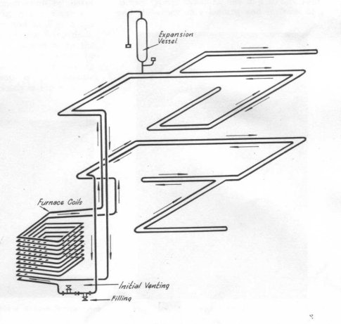
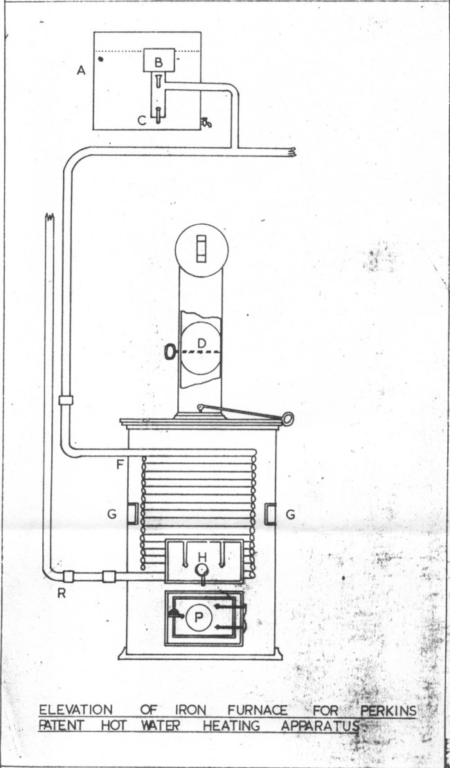
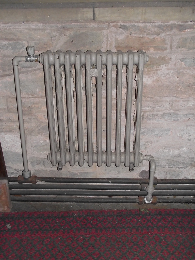
The system is simple in its design and is formed as an endless loop of pipe, part of which is coiled around inside a brickwork furnace. The pipework is hydraulic quality tubing with the system closed and sealed. Sealing the system allowed it to operate at working pressures of up to 300 pounds per square inch and temperatures as high as 300°F.
Isometric layout of 2- circuit pipework distribution system
The system used gravity as the means of circulating the hot water around the pipework. The length of each circuit was therefore limited by the small diameter pipe size and needed to be kept to a maximum of 500 feet. Up to 15 per cent of this circuit was coiled inside the brickwork furnace. Should this length of pipework not be sufficient for the heating of the building then the endless loop was made longer in multiples of 500 feet with each circuit length returning to the brickwork furnace.
Each sealed circuit needed to be fitted with an expansion tube which had to be fitted at the top (the highest point) of the system. These closed expansion vessels allowed the heated water to expand into the vessel from the bottom and compress the air inside the vessel, thus exerting an artificial pressure on the water. Most systems were initially filled from the bottom of the pipework circuit until the top-up fill point was reached.
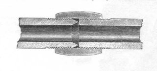
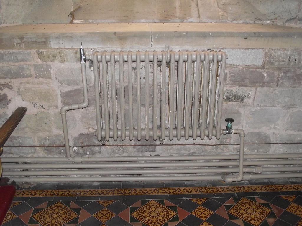
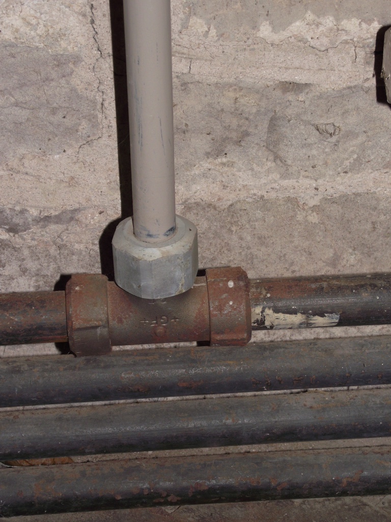
The tubing used is of small size approx. 1" outside diameter with the lengths of tubing joined together with right and left hand threaded pipe sockets. The sockets were of unusual design in that no jointing material was needed. The sockets used a metal to metal joint with one end of the threaded tube being chamfered. This was then pulled tight up to the flat faced end of the other length of tube.
Letter from Mr T Bevington of King William Street London. 6th August 1839.
"The warm water apparatus you put up for me in January 1835 which warms my countryhouse and seven warehouses has completed the object to my entire satisfaction, being both economical in fuel and cleanly in the use"
Letter from Messrs Smee & Son Wholesale Cabinet Makers & Upholsterers.
23rd September 1839
"The Patent hot water apparatus for warming our workshops and ware rooms and for heating our feather store, have been quite successful during the period we have used it, namely five years. We think it more than probable had we the same business to do again, that we should still adopt the same method; and we shall with pleasure show anyone the apparatus if it will be of service to you. Our apparatus is a quarter of a mile on extent"
THE TIMES NEWSPAPER ARTICLE
The Perkins high pressure high temperature (HPHW) hot water heating system did however have some problems early in its life. These are quite forcibly described in a letter written to the editor of THE TIMES newspaper which appeared on Saturday 20th November 1841. The letterwriter supplies a list of buildings which details a number of them that had experienced fires supposedly caused by direct contact with the very high surface temperatures of the pipes.
Wilson.Casey and Phillips, Spitalfields - Warehouse set on fire by pipes becoming red hot
Sir Hussey Vivian. Glynn House -ditto-
Mr Barbour Manchester -ditto-
Craft and Steel, Manchester Manufactory destroyed by fire in consequence of bursting of the apparatus and the fire being scattered; the damage estimated at £20,000
Museum of Natural History Manchester. Set on fire in several places by the pipes becoming overheated.
Birch chapel Manchester matting and cushions burnt by pipes becoming too hot
Unitarian Chapel Manchester -ditto-
Williams, Deacon & Co pipes set fire to joist of building; speedily extinguished without damage.
Lothbury Church Expansion pipe burst and scolded the charity children.
Lady Cockerill Seinscote apparatus burst twice during the night and caused great alarm and some damage.
Sir T Cullum Bury apparatus burst twice and destroyed much glass in the house.
Mr Ingliss Dulwich burst in furnace with damage.
Camberell Workhouse burst with much damage.
Timothy Smith & Co Birmingham -ditto-
Horticultural Gardens Chiswick -ditto-
Mr Hemming Dulwich -ditto-
Sir J Lubbock Mitcham Grove -ditto-
Guardian Fire Office -ditto-
Mr Debouverie Englefield -ditto-
Lord Beresford Bedgebury -ditto-
Inner Temple Hall -ditto
Duke of Wellington Strathfieldsays -ditto-
Marlborough House -ditto-
Why these systems went out of fashion most likely is to have been the increasing popularity of low pressure hot water heating systems which had greater flexibility to suit the more complex buildings of the 20th century. The discovery of the reason for the likely cause of its fall from grace still remains a matter of interest to the author. Another possible reason could be, that insurance companies were increasing their premiums for insuring this type of system due to the incidence of fires caused, or maybe they were even refusing to provide cover.
It states in the letter to The Times “It is a subject which alike concerns the fire insurance companies as well as individuals; and it is a well known fact, that since the commencement of the present year, in consequence of the fires which occurred in Manchester, as already stated, many insurance companies both in London and in the country have refused to insure at any premium whatever buildings heated by some of the plans which have been here described”
Looking at the list of buildings damaged, one of the buildings mentioned was the Guardian Fire Office, and this could not have been good news for the Perkins company. However, these problems must have been overcome as Perkins’s systems were still being installed into the 1890’s and beyond.
However, Angier March Perkins responds to the letter writer's allegations giving a robust defence of his invention of the High Pressure heating system.
To read the letters and responding replies visit webpage The Times Newspaper